Reelmaster 7000
Hydraulic System
Page 4 -- 72
Filtering Closed--Loop Traction Circuit
Filtering of a closed--loop hydraulic system after a major
component failure (e.g. traction (piston) pump or front
wheel motor) is a requirement to prevent debris from
transmitting throughout the system. If a closed--loop hy-
draulic system filtering tool is not used to ensure system
cleanliness, repeat failures, as well as subsequent dam-
age to other hydraulic components in the affected sys-
tem, will occur. To effectively remove contamination
from closed--loop traction circuit, use of the Toro high
flow hydraulic filter and hydraulic hose kits are recom-
mended (see Special Tools in this chapter).
1. Park machine on a level surface with engine stopped
and key removed from ignition switch.
2. Raise and support machine so all wheels are off the
ground (see Jacking Instructions in Chapter 1 -- Safety).
NOTE:
If front wheel or rear axle motor was replaced,
install high flow filter to the inlet of new motor instead of
to the traction pump fitting. This will prevent system con-
tamination from entering and damaging the new motor.
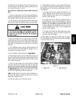
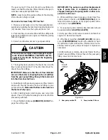
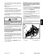
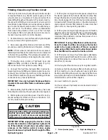
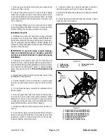
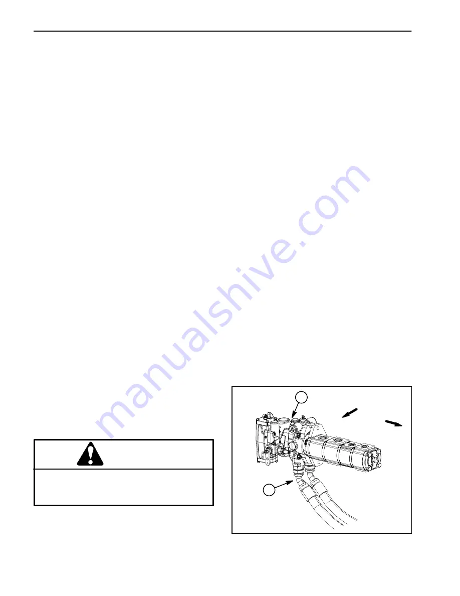
3. Thoroughly clean junction of hydraulic hose and
right
side fitting on bottom of traction pump (Fig. 50).
Disconnect hose from right side pump fitting.
4. Connect Toro high flow hydraulic filter in series be-
tween traction pump fitting and disconnected hose. Use
hydraulic hose kit (see Special Tools in this chapter) to
connect filter to machine. Make sure that fitting and hose
connections are properly tightened.
IMPORTANT: Use only hydraulic fluids specified in
Operator’s Manual. Other fluids could cause system
damage.
5. After installing high flow filter to machine, check and
fill hydraulic reservoir with new hydraulic oil as required.
6. Start engine and run at idle speed. Check for any hy-
draulic leakage from filter and hose connections. Cor-
rect any leaks before proceeding.
CAUTION
All wheels will be off the ground and rotating dur-
ing this procedure. Make sure machine is well
supported so it will not move and accidentally
fall to prevent injuring anyone around machine.
IMPORTANT: While engaging the traction circuit,
monitor the indicator on the high flow hydraulic fil-
ter. If the indicator should show red, either reduce
pressure on the traction pedal or reduce engine
speed to decrease hydraulic flow through the filter.
7. With engine running at low idle speed, slowly move
the traction pedal to the forward direction to allow flow
through the traction circuit and high flow filter. Keep trac-
tion circuit engaged for five (5) minutes while gradually
increasing both forward pressure on traction pedal and
engine speed. Monitor filter indicator to make sure that
green color is showing during operation.
8. With engine running at high idle speed and traction
pedal moved to the forward direction, periodically apply
brakes to increase pressure in traction circuit. While
monitoring filter indicator, continue this process for an
additional five (5) minutes.
IMPORTANT: If using a filter that is not the bi--direc-
tional Toro high flow filter, do not press the traction
pedal in the reverse direction. If flow is reversed
when using a filter that is not bi--directional, debris
from the filter will re--enter the traction circuit.
9. With engine running at high idle speed, alternately
move traction pedal from forward to reverse. While mon-
itoring filter indicator, continue this process for an addi-
tional five (5) minutes.
10.Shut engine off and remove key from ignition switch.
11.Remove high flow hydraulic filter and hydraulic hose
kit from machine. Connect hydraulic hose to right side
traction pump fitting. Make sure to properly tighten hose
(see Hydraulic Hose and Tube Installation in the Gener-
al Information section of this chapter).
12.Lower machine to ground.
13.Check oil level in hydraulic reservoir and add correct
oil if necessary.
1. Piston (traction) pump
2. Right side fitting/hose
Figure 50
FRONT
RIGHT
1
2
Summary of Contents for Reelmaster 7000
Page 2: ...Reelmaster 7000 This page is intentionally blank ...
Page 4: ...Reelmaster 7000 This page is intentionally blank ...
Page 10: ...Reelmaster 7000 Page 1 6 Safety This page is intentionally blank ...
Page 12: ...0 09375 Reelmaster 7000 Page 2 2 Product Records and Maintenance Equivalents and Conversions ...
Page 34: ...Reelmaster 7000 Page 3 18 Kubota Diesel Engine This page is intentionally blank ...
Page 36: ...Reelmaster 7000 Hydraulic System Page 4 2 This page is intentionally blank ...
Page 45: ...Reelmaster 7000 Hydraulic System Page 4 11 This page is intentionally blank Hydraulic System ...
Page 115: ...Reelmaster 7000 Hydraulic System Page 4 81 This page is intentionally blank Hydraulic System ...
Page 131: ...Reelmaster 7000 Hydraulic System Page 4 97 This page is intentionally blank Hydraulic System ...
Page 139: ...Reelmaster 7000 Hydraulic System Page 4 105 This page is intentionally blank Hydraulic System ...
Page 147: ...Reelmaster 7000 Hydraulic System Page 4 113 This page is intentionally blank Hydraulic System ...
Page 151: ...Reelmaster 7000 Hydraulic System Page 4 117 This page is intentionally blank Hydraulic System ...
Page 168: ...Reelmaster 7000 Hydraulic System Page 4 134 This page is intentionally blank ...
Page 214: ...Reelmaster 7000 Page 5 46 Electrical System This page is intentionally blank ...
Page 247: ...Reelmaster 7000 Page 7 3 Chassis This page is intentionally blank Chassis ...
Page 264: ...Reelmaster 7000 Page 7 20 Chassis This page is intentionally blank ...
Page 271: ...Reelmaster 7000 DPA Cutting Units Page 8 7 This page is intentionally blank DPA Cutting Units ...
Page 304: ...Reelmaster 7000 DPA Cutting Units Page 8 40 This page is intentionally blank ...
Page 306: ...Reelmaster 7000 Foldout Drawings Page 9 2 This page is intentionally blank ...
Page 310: ...Page 9 6 Reelmaster 7000 Main Wire Harness ...
Page 312: ...Page 9 8 Reelmaster 7000 Seat and Console Wire Harness ...
Page 314: ...Page 9 10 Reelmaster 7000 Power Center Wire Harness ...

