Reelmaster 7000
Page 5 -- 7
Electrical System
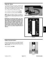
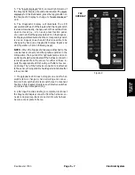
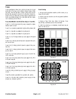
5. The “inputs displayed” LED, on lower right column of
the Diagnostic Display, should be illuminated. If “outputs
displayed” LED is illuminated, press the toggle button on
the Diagnostic Display to change to “inputs displayed”
LED.
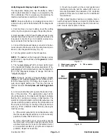
6. The Diagnostic Display will illuminate the LED
associated with each of the inputs when that input switch
is closed. Individually, change each of the switches from
open to closed (i.e., sit on seat, press traction pedal,
etc.), and note that the appropriate LED on the Diagnos-
tic Display will illuminate when the corresponding switch
is closed. Repeat on each switch that is possible to be
changed by hand (see Diagnostic Display Inputs and
LED Operation chart on following page).
NOTE:
When the Diagnostic Display is attached to the
wire harness connector and the ignition switch is in the
ON position, the input LED for hydraulic temp and cool-
ant temp should be illuminated. If the harness connector
is disconnected from the sensor for either of these in-
puts, the appropriate LED should go off after a few sec-
ond delay. Then, if the harness connector is reattached
to the sensor, the input LED should again illuminate after
a few seconds.
7. If appropriate LED does not toggle on and off when
switch state is changed, check all wiring and connec-
tions to that switch and/or test switch (see Component
Testing in this chapter). Replace any defective switches
and repair any damaged wiring.
8. After input functions testing is complete, disconnect
the Diagnostic Display connector from the harness con-
nector and plug loop--back connector into wire harness.
Secure access plate to frame.
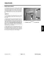
Figure 9
TEC
OVERLAY
Electrical System
Summary of Contents for Reelmaster 7000
Page 2: ...Reelmaster 7000 This page is intentionally blank ...
Page 4: ...Reelmaster 7000 This page is intentionally blank ...
Page 10: ...Reelmaster 7000 Page 1 6 Safety This page is intentionally blank ...
Page 12: ...0 09375 Reelmaster 7000 Page 2 2 Product Records and Maintenance Equivalents and Conversions ...
Page 34: ...Reelmaster 7000 Page 3 18 Kubota Diesel Engine This page is intentionally blank ...
Page 36: ...Reelmaster 7000 Hydraulic System Page 4 2 This page is intentionally blank ...
Page 45: ...Reelmaster 7000 Hydraulic System Page 4 11 This page is intentionally blank Hydraulic System ...
Page 115: ...Reelmaster 7000 Hydraulic System Page 4 81 This page is intentionally blank Hydraulic System ...
Page 131: ...Reelmaster 7000 Hydraulic System Page 4 97 This page is intentionally blank Hydraulic System ...
Page 139: ...Reelmaster 7000 Hydraulic System Page 4 105 This page is intentionally blank Hydraulic System ...
Page 147: ...Reelmaster 7000 Hydraulic System Page 4 113 This page is intentionally blank Hydraulic System ...
Page 151: ...Reelmaster 7000 Hydraulic System Page 4 117 This page is intentionally blank Hydraulic System ...
Page 168: ...Reelmaster 7000 Hydraulic System Page 4 134 This page is intentionally blank ...
Page 214: ...Reelmaster 7000 Page 5 46 Electrical System This page is intentionally blank ...
Page 247: ...Reelmaster 7000 Page 7 3 Chassis This page is intentionally blank Chassis ...
Page 264: ...Reelmaster 7000 Page 7 20 Chassis This page is intentionally blank ...
Page 271: ...Reelmaster 7000 DPA Cutting Units Page 8 7 This page is intentionally blank DPA Cutting Units ...
Page 304: ...Reelmaster 7000 DPA Cutting Units Page 8 40 This page is intentionally blank ...
Page 306: ...Reelmaster 7000 Foldout Drawings Page 9 2 This page is intentionally blank ...
Page 310: ...Page 9 6 Reelmaster 7000 Main Wire Harness ...
Page 312: ...Page 9 8 Reelmaster 7000 Seat and Console Wire Harness ...
Page 314: ...Page 9 10 Reelmaster 7000 Power Center Wire Harness ...

