Rev. A
Reelmaster 7000
Hydraulic System
Page 4 -- 45
NOTE:
Adjustable relief valve (RV) in the 4WD/2WD
control manifold reduces rear axle motor pressure
created in down hill, dynamic braking conditions to pre-
vent rear wheel lock up.
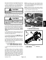
Procedure for Rear Traction Circuit Relief (RV) Pres-
sure Test
1. Make sure hydraulic oil is at normal operating tem-
perature by operating the machine for approximately ten
(10) minutes. Make sure the hydraulic tank is full.
2. Park machine on a level surface with the cutting units
lowered and off. Make sure engine is off and the parking
brake is engaged.
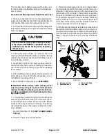
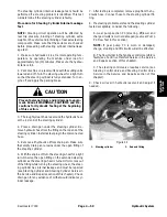
CAUTION
Prevent personal injury and/or damage to equip-
ment. Read all WARNINGS, CAUTIONS and Pre-
cautions for Hydraulic Testing at the beginning
of this section.
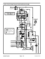
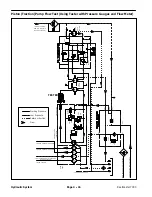
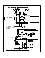
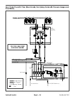
3. Measure and record traction circuit pressure redu-
cing valve (PR) pressure (see Traction Circuit Pressure
Reducing Valve (PR) Pressure Test in this section).
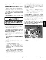
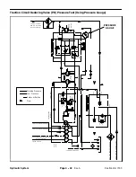
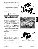
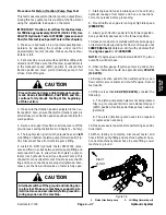
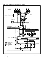
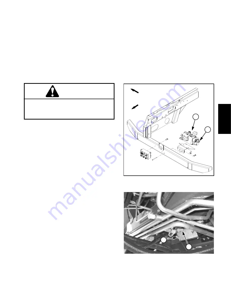
4. Connect a 1000 PSI (70 bar) pressure gauge to test
fitting (port G) on rear side of 4WD/2WD control manifold
under front of machine (Figs. 34 and 35). This is the
same pressure gauge position as used to measure trac-
tion circuit pressure reducing valve (PR) pressure.
5. After installing pressure gauge, start engine and run
at low idle speed. Check for hydraulic leakage and cor-
rect before proceeding with test.
6. Move throttle to high idle speed
(2850 RPM)
. Make
sure that mow speed limiter is in the mow (4WD) posi-
tion. Release parking brake.
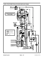
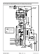
7. Operate the machine in mow speed (4WD) with the
cutting units lowered. Drive down a slope in a forward di-
rection and decrease pressure on the traction pedal
while carefully monitoring the pressure gauge. Pressure
should increase until relief valve (RV) lifts.
8. Stop engine and record test results.
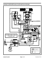
9. Relief (RV) pressure should be
at least 100 PSI (7
bar) higher than the traction circuit pressure redu-
cing valve (PR) pressure and also be between 520
and 570 PSI (36 to 39 bar)
(e.g. if the pressure reducing
valve (PR) pressure is 450 PSI (31 bar), relief (RV) pres-
sure should be from 550 to 570 PSI (38 to 39 bar)).
NOTE:
Rear traction circuit relief (RV) pressure should
be at least 100 PSI (7 bar) higher than traction circuit re-
ducing (PR) pressure. If the difference in these pres-
sures is less than 100 PSI (7 bar), reverse traction
performance may be affected.
10.If specification is
not
met, clean or adjust relief valve
(RV) which is located on the left side of the 4WD/2WD
control manifold in the RV port (Fig. 34) (see Adjust Con-
trol Manifold Relief Valves in the Adjustments section of
this chapter for valve adjustment procedure). Recheck
relief (RV) pressure after adjustment.
11. When testing is completed, disconnect pressure
gauge from test port. Install dust cap to test port fitting.
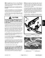
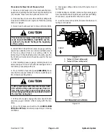
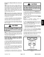
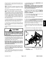
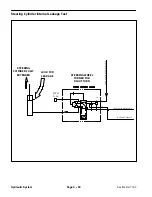
1. 4WD/2WD manifold
2. Relief valve (RV)
Figure 34
1
2
FRONT
RIGHT
1. 4WD/2WD manifold
2. Test fitting (port G)
Figure 35
1
2
Hydrauli
c
S
yst
em
Summary of Contents for Reelmaster 7000
Page 2: ...Reelmaster 7000 This page is intentionally blank ...
Page 4: ...Reelmaster 7000 This page is intentionally blank ...
Page 10: ...Reelmaster 7000 Page 1 6 Safety This page is intentionally blank ...
Page 12: ...0 09375 Reelmaster 7000 Page 2 2 Product Records and Maintenance Equivalents and Conversions ...
Page 34: ...Reelmaster 7000 Page 3 18 Kubota Diesel Engine This page is intentionally blank ...
Page 36: ...Reelmaster 7000 Hydraulic System Page 4 2 This page is intentionally blank ...
Page 45: ...Reelmaster 7000 Hydraulic System Page 4 11 This page is intentionally blank Hydraulic System ...
Page 115: ...Reelmaster 7000 Hydraulic System Page 4 81 This page is intentionally blank Hydraulic System ...
Page 131: ...Reelmaster 7000 Hydraulic System Page 4 97 This page is intentionally blank Hydraulic System ...
Page 139: ...Reelmaster 7000 Hydraulic System Page 4 105 This page is intentionally blank Hydraulic System ...
Page 147: ...Reelmaster 7000 Hydraulic System Page 4 113 This page is intentionally blank Hydraulic System ...
Page 151: ...Reelmaster 7000 Hydraulic System Page 4 117 This page is intentionally blank Hydraulic System ...
Page 168: ...Reelmaster 7000 Hydraulic System Page 4 134 This page is intentionally blank ...
Page 214: ...Reelmaster 7000 Page 5 46 Electrical System This page is intentionally blank ...
Page 247: ...Reelmaster 7000 Page 7 3 Chassis This page is intentionally blank Chassis ...
Page 264: ...Reelmaster 7000 Page 7 20 Chassis This page is intentionally blank ...
Page 271: ...Reelmaster 7000 DPA Cutting Units Page 8 7 This page is intentionally blank DPA Cutting Units ...
Page 304: ...Reelmaster 7000 DPA Cutting Units Page 8 40 This page is intentionally blank ...
Page 306: ...Reelmaster 7000 Foldout Drawings Page 9 2 This page is intentionally blank ...
Page 310: ...Page 9 6 Reelmaster 7000 Main Wire Harness ...
Page 312: ...Page 9 8 Reelmaster 7000 Seat and Console Wire Harness ...
Page 314: ...Page 9 10 Reelmaster 7000 Power Center Wire Harness ...


