background image

Operation

Note:

Determine the left and right sides of the machine

from the normal operating position.

Preparing for Work

Before operating the machine on the job site, review the
following items:

Gather all relevant information available about the job
site before you begin working.

Review all blueprints and other plans, and identify all
existing or proposed structures, characteristics of the
landscape, and other proposed jobs in the area scheduled
at the same time as your job.

Note the following items at the job site:

Changes in elevation in the proposed work area

The condition and type of soil in the proposed work
area

Locations of structures, water, railroad tracks, and
other obstructions that you will need to work near
or around

Utility markers, meters, and poles

If the work site is near or on a roadway with traffic,
call the local authorities regarding proper safety
procedures and regulations.

Access to the site

Call your local One-Call service (811 in the US) or the
One-Call referral number (888-258-0808 in the US and
Canada) and ask the participating utility companies to
locate and mark their underground utility lines. Also call
utility providers that are not part of the One-Call system.

Adding Fuel to the Engine

Use ultra-low sulfur diesel (ULSD) fuel in the engine. Using
other fuels can cause a loss of engine power and high fuel
consumption.

Important:

Do not use kerosene or gasoline instead of

diesel fuel; otherwise, you will damage the engine.

Use only diesel fuel for the machine that meets Specification
D975 of the American Society for Testing and Materials
International. See your diesel fuel distributor.

Use only clean, fresh diesel fuel or biodiesel fuels with low
(<500 ppm) or ultra low (<15 ppm) sulfur content. The
minimum cetane rating should be 40. Purchase only enough
fuel that you expect to use within 30 days to ensure that it
stays fresh.

Fuel tank capacity:

75.7 L (20 US gal)

Use summer-grade diesel fuel (No. 2-D) at temperatures
above 20°F (-7°C) and winter-grade diesel fuel (No. 1-D or
No. 1-D/2-D blend) below 20°F (-7°C). Using winter-grade
fuel at lower temperatures provides a lower flash point and

cold flow characteristics, which aid in starting the engine and
help prevent clogging the fuel filter.

Using summer-grade fuel above 20° F (-7°C) contributes
toward a longer fuel pump life and increased power compared
to using winter-grade fuel.

WARNING

Fuel is harmful or fatal if swallowed. Long-term
exposure to fuel vapors can cause serious injury
and illness.

Avoid prolonged breathing of vapors.

Keep your face away from nozzle and fuel tank
or conditioner opening.

Keep fuel away from your eyes and skin.

DANGER

In certain conditions, fuel is extremely flammable
and highly explosive. A fire or explosion from fuel
can burn you and others and can damage property.

Fill the fuel tank outdoors in an open area when
the engine is cold. Wipe up any fuel that spills.

Never fill the fuel tank inside an enclosed trailer.

Never smoke when handling fuel, and stay away
from an open flame or where fuel fumes may be
ignited by a spark.

Store fuel in an approved container, and keep
it out of the reach of children. Never buy more
than a 30-day supply of fuel.

Do not operate without entire exhaust system in
place and in proper working condition.

In certain conditions, fueling can release static electricity and
cause a spark, which can ignite the fuel vapors. A fire or
explosion from fuel can burn you and others and can damage
property.

Always place fuel containers on the ground, away from
your vehicle before filling.

Do not fill fuel containers inside a vehicle or on a truck
or trailer bed, because interior carpets or plastic truck
bed liners may insulate the container and slow the loss
of any static charge.

When practical, remove the equipment from the truck
or trailer, and refuel the equipment with its wheels on
the ground.

If refuelling the equipment with its wheels on the ground
is not possible, then refuel such equipment on a truck or
trailer from a portable container rather than from a fuel
dispenser nozzle.

If you must use a fuel dispenser nozzle, keep the nozzle in
contact with the rim of the fuel tank or container opening
at all times until fueling is complete.

22

Summary of Contents for RT600

Page 1: ...Unit Model No 25430 Serial No 314000001 and Up Model No 25430A Serial No 314000001 and Up Model No 25430C Serial No 314000001 and Up Model No 25430W Serial No 314000001 and Up Register at www Toro co...

Page 2: ...y other material other than soil Read this information carefully to learn how to operate and maintain your product properly and to avoid injury and product damage You are responsible for operating the...

Page 3: ...symbol Figure 2 which means Caution Warning or Danger personal safety instruction Failure to comply with the instruction may result in personal injury or death Important This machine was manufactured...

Page 4: ...rly installed Use extra care when handling fuels They are flammable and vapors are explosive Use only an approved container Do not remove the fuel cap or add fuel with the engine running Allow the eng...

Page 5: ...stop and remove the key whenever you adjust clean or repair the machine Do not touch parts that may be hot from operation Allow them to cool before attempting to maintain adjust or service the machin...

Page 6: ...ucting electricity Do not attempt to leave the machine Note You will be safe as long as you do not leave the seat of the machine Touching any part of the machine while contacting the ground may electr...

Page 7: ...l danger Replace any decal that is damaged or lost Figure 3 Decal Map Top view 1 Decal 125 8470 under the hood 5 Decal 125 8472 9 Decal 125 8478 13 Decal 125 6699 2 Decal 125 8483 6 Decal 125 6695 10...

Page 8: ...cal 125 8480 5 Decal 125 8481 7 Decal 125 6689 2 Decal 125 4963 4 Decal 125 8482 6 Decal 125 8478 125 4963 1 Warning do not touch hot surfaces 125 6683 1 Pull out for fastest speed 4 Decrease speed 2...

Page 9: ...machine is on a slope 125 6695 1 Trencher chain forward 9 Engage the vibratory plow 2 Backfill blade pivot left 10 Trencher chain reverse 3 Backfill blade raise 11 Backfill blade tilt right 4 Backfil...

Page 10: ...ntil you have called local utilities 3 Warning always wear a seat belt when operating the machine 8 Read the Operator s Manual for information on starting the engine 1 Engage the parking brake 2 Set t...

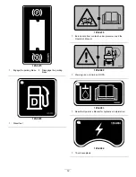
Page 11: ...g only when moving the machine forward in 4th gear 125 8472 1 Engine stop 3 Engine start 2 Engine run 125 8473 1 Explosion hazard wear eye protection 3 Fire hazard keep open flames away 2 Chemical bur...

Page 12: ...rking brake 125 8478 1 Diesel fuel 125 8479 1 Burn hazard from contents under pressure read the Operator s Manual 125 8480 1 Warning do not climb on ROPS 125 8483 1 Read the Operator s Manual for hydr...

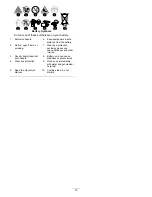
Page 13: ...fire open flame or smoking 7 Wear eye protection explosive gases can cause blindness and other injuries 3 Caustic liquid chemical burn hazard 8 Battery acid can cause blindness or severe burns 4 Wear...

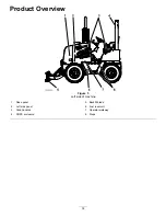
Page 14: ...Product Overview Figure 5 Left side of machine 1 Nose panel 5 Backfill blade 2 Left side panel 6 Fuel reservoir 3 Grab handles 7 Operator walkway 4 ROPS enclosure 8 Steps 14...

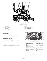
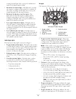
Page 15: ...itch to the Run position before you start Warning Lights The locations of these lights are shown in Figure 7 G022146 7 8 1 6 2 3 4 5 Figure 7 Instrument Cluster Lights 1 Engine intake preheat light 5...

Page 16: ...lowing controls are in the Neutral or the Stop position Traction control pedal Utility traction lever Attachment control lever Gauges The locations of these gauges are shown in Figure 8 G022145 1 6 2...

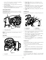
Page 17: ...ne Start Turn the key to this position to start the engine Throttle Knob Use the throttle knob Figure 11 to change the engine speed as follows Figure 11 1 Throttle button 3 Throttle lock 2 Throttle kn...

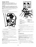
Page 18: ...the utility traction lever is detented You must move the lever out of the detent to move the lever forward or rearward The utility traction lever Figure 13 has 3 positions Forward Neutral and Reverse...

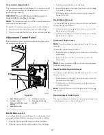
Page 19: ...k back to raise the blade Push the joystick to the right away from you to swing the blade to the right Pull the joystick to the left toward you to swing the blade to the left Backfill Blade Tilt Lever...

Page 20: ...ment control lever from the Neutral position otherwise the engine will stop in 1 second Rear Wheel Position Indicator This indicator Figure 16 shows the position of the rear wheels when you set the re...

Page 21: ...ch The battery disconnect switch is located behind the right engine cowl Figure 18 use it to electrically disconnect the battery from the machine Figure 18 1 Battery On position 2 Battery Off position...

Page 22: ...el No 1 D or No 1 D 2 D blend below 20 F 7 C Using winter grade fuel at lower temperatures provides a lower flash point and cold flow characteristics which aid in starting the engine and help prevent...

Page 23: ...e fuel tank cap and tighten it securely by hand Checking the Engine Oil Level Service Interval Before each use or daily The engine is shipped with oil in the crankcase however check the oil level befo...

Page 24: ...x Low Pour Point Anti wear Hydraulic Fluid ISO VG 46 Material Properties St 40 C 104 F 44 to 48 Viscosity ASTM D445 St 100 C 212 F 7 9 to 8 5 Viscosity Index ASTM D2270 140 to 160 Pour Point ASTM D97...

Page 25: ...t or cold weather take the necessary precautions refer to Operating the Machine in Extreme Conditions page 26 7 Turn the key switch to the On position and check that the controls in neutral the parkin...

Page 26: ...to Checking the Engine Oil Level page 23 and Servicing the Engine Oil and Filter page 38 Operating the Machine in Extreme Conditions Both hot and cold weather place unusual demands upon the machine an...

Page 27: ...rating the Parking Brake 1 Push the parking brake switch Figure 24 up to apply the parking brake Figure 24 1 Parking brake 2 Push the parking switch down to release the parking brake Note The parking...

Page 28: ...er all attachments to the ground 3 Set the parking brake 4 If the machine has been operating under a heavy load decrease the engine speed to 1 4 throttle for 2 minutes to cool the engine 5 Push in the...

Page 29: ...ate the Machine After starting the engine but before operating the machine at the work site do the following Ensure that the ROPS and the seat belt are properly installed and in good working order Ens...

Page 30: ...nd remove the key 8 Block the front and rear wheels of the machine 9 Fasten the front of the machine to the trailer using chains and a binder Figure 29 Note Use the front axle to secure the machine G0...

Page 31: ...ng connected to the cylinder fitting 2 Hydraulic brake hose 4 Hand pump 2 Connect a hydraulic hand pump capable of producing 350 psi to the brake cylinder Figure 30 3 Operate the hand pump until the b...

Page 32: ...turn the spoils back into the trench with the backfill blade refer to Using the Backfill Blade page 29 2 Return the spoils into the trench A Move the machine to the end of the trench a few feet meters...

Page 33: ...lant level in the radiator Every 200 hours Grease the front and rear axles Every 250 hours Change the engine oil Change the engine oil filter Check the oil level in the wheel hubs Check the oil level...

Page 34: ...the covers or guards in place 1 Park the machine on a level surface 2 Lower all attachments and stop the engine and remove the key 3 Allow the engine to cool 2 or 3 minutes 4 Remove the right side pa...

Page 35: ...back universal joint 2 Grease fitting sliding joint 3 Connect the grease gun to the grease fitting for the universal joint at the forward end of the drive shaft and apply 2 or 3 pumps of grease to the...

Page 36: ...ne to cool for 2 or 3 minutes Accessing the Engine Removing the Side Panels 1 If the optional backhoe is installed perform the following substeps to remove the left side panel otherwise skip to step 2...

Page 37: ...the front end of the walkway to its original position Figure 35 B Align the hole in the walkway with the hole in the walkway support bracket Figure 35 C Install the retaining pin through the holes Re...

Page 38: ...hrough the holes in the frame of the backhoe and the seat post Figure 38 C Install the hairpin into the hole in the seat lock pin Figure 38 5 Install the left and right side panels on the machine refe...

Page 39: ...r to Removing the Side Panels page 36 4 Remove the dipstick and wipe clean it with a clean cloth Figure 42 Figure 42 1 Dipstick 2 Dipstick tube 5 Insert the dipstick into the dipstick tube pull the di...

Page 40: ...surface of the oil filter adapter where the oil filter seats 5 Fill the new oil filter with the specified engine oil allow the filter element to saturate with the oil and then pour out the excess oil...

Page 41: ...steps 1 and 2 C If the restricted air cleaner light still comes on replace the secondary air cleaner element refer to Replacing the Secondary Element page 42 Removing the Air cleaner Cover 1 Remove t...

Page 42: ...ent date and the engine hours on the end of the element with a permanent marking pen 6 Insert the new primary air cleaner element into the air cleaner housing Figure 50 Note Ensure that the air cleane...

Page 43: ...n pan under the secondary fuel filter Figure 52 Figure 52 1 Secondary fuel filter 2 Drain valve 3 Rotate the drain valve at the bottom of the secondary fuel filter 2 or 3 turns counterclockwise and dr...

Page 44: ...he fuel tank Figure 54 Replacing the Fuel Filters Replacing the Secondary Fuel Filter Service Interval Every 500 hours 1 Remove the left side panel refer to Removing the Side Panels page 36 2 Remove t...

Page 45: ...s over the hose fitting of the primary fuel filter and tighten the hose clamps Figure 55 6 Bleed the fuel system refer to Bleeding the Fuel System page 45 7 Start the engine and check for leaks at the...

Page 46: ...ways wear face protection protective gloves and protective clothing WARNING A battery contains sulfuric acid which can cause serious burns and they can produce explosive gases Avoid contact with skin...

Page 47: ...page 25 Note If the engine starts and then stops do not operate the starter motor until the starter motor stops turning Do not operate the starter motor for more than 30 seconds at one time Wait 30 se...

Page 48: ...o Removing the Side Panels page 36 2 Rotate the battery disconnect switch counterclockwise to the Off position Figure 60 Figure 60 1 Battery disconnect switch in the On position 2 Battery disconnect s...

Page 49: ...hutoff valve and a self locking chuck Note Before you add air ensure that the tire is properly installed on the machine or put the wheel in a restraining device such as a tire inflation cage 2 Remove...

Page 50: ...the drain port in the wheel hub Figure 64 5 Remove the plug from the wheel hub Figure 64 6 Check that the oil level is at the bottom of the threads of the oil port Figure 64 If the oil level is too hi...

Page 51: ...les Service Interval After the first 100 hours Every 250 hours 1 Place a drain pan under the pinion housing of the axle 2 Remove the plug from the sight port in the pinion housing of the axle Figure 6...

Page 52: ...8 and Figure 69 Note Allow the oil to drain completely from the pinion housing and axle 3 Clean the threads of the plugs 4 Apply PTFE thread sealing tape to the threads of the plugs 5 Install one of t...

Page 53: ...140 API classification level GL4 Transmission oil capacity approximately 1 7 L 1 8 US qt Toro Premium Gear Oil is available from an Authorized Toro Service Dealer See the parts catalog for part number...

Page 54: ...gure 76 1 Rear axle 3 Breather fitting 2 Breather port 2 Remove the breather from the front axle Figure 75 3 Remove the breather from the rear axle Figure 76 4 Clean the breathers with a cleaning solv...

Page 55: ...Reservoir 2 Coolant level halfway between the Add and Full marks Note Ensure that the coolant level is between the Add mark and the Full mark on the reservoir Figure 77 5 Add the specified coolant un...

Page 56: ...on of the cooling system for leaks damage dirt and loose hoses and clamps Clean repair tighten and replace the components as necessary Checking the Concentration of the Coolant Service Interval Every...

Page 57: ...Note Use cleaning solution of sodium carbonate and water or a commercially available equivalent Follow the directions that come with the cleaning solution Figure 81 1 Coolant system cleaning solution...

Page 58: ...above 37 C 34 F If the ambient temperature is lower adjust the mixture Use a mixture of ethylene glycol and water in the machine all year 1 Remove the radiator cap Figure 78 and Figure 79 2 Open the...

Page 59: ...fer to Installing the Side Panels page 37 Checking the Tension of the Belt Service Interval Every 1 000 hours 1 Remove the right side panel refer to Removing the Side Panels page 36 2 Place a straight...

Page 60: ...placing the Engine Drive Belt Removing the Belt 1 Remove the left and right side panels refer to Removing the Side Panels page 36 2 Loosen the nut and bolt at the pivot point for the alternator Figure...

Page 61: ...nt of the fan Figure 90 2 Move a fan blade to the 4 o clock position 3 Align the belt between the tip of the fan blade and the opening in the shroud Figure 89 4 Move the belt rearward and past the tip...

Page 62: ...140 to 160 Pour Point ASTM D97 37 C 34 F to 45 C 49 F FZG Fail stage 11 or better Water content new fluid 500 ppm maximum Industry Specifications Vickers I 286 S Quality Level Vickers M 2950 S Qualit...

Page 63: ...5 Stop the engine and remove the ignition key 6 Check around the pressure and return filters for leaks 7 Check the drain plug for leaks 8 Check the level of the hydraulic fluid Changing the Hydraulic...

Page 64: ...esidual hydraulic fluid to drain in the container Figure 95 Note Use a tapered center punch or awl to puncture the filter case 3 Rotate the hydraulic return filter counterclockwise and remove the filt...

Page 65: ...the machine 1 Check that the 8 bolts that secure the ROPS bar to the chassis of the machine are torqued to 24 4 to 26 1 N m 216 to 231 in lb refer to Figure 96 Figure 96 1 ROPS bar 2 Bolt 2 Check tha...

Page 66: ...Dirt and Debris from the Machine Important Operating the engine with blocked screens dirty or plugged cooling fins and or cooling shrouds removed will result in engine damage from overheating 1 Lower...

Page 67: ...solution C Coat the cable terminals and battery posts with Grafo 112X skin over grease Toro Part No 505 47 or equivalent grease D Slowly recharge the battery every 60 days for 24 hours to prevent lead...

Page 68: ...k the battery oil viscosity and starting motor contact your Authorized Service Dealer 9 The air cleaning system elements are dirty 9 Service the air cleaning system elements 10 The fuel filter is clog...

Page 69: ...en 3 The engine oil level is either too low or too high 3 Either add or drain the engine oil until the oil level is at the Full mark 4 The machine is under an excessive load 4 Reduce the load on the m...

Page 70: ...he air cleaning system elements 4 There is dirt or water in the fuel system 4 Drain and flush the fuel system add fresh fuel 5 The engine overheats 5 Check the engine oil level and add oil as needed a...

Page 71: ...Notes 71...
Page 72: ...ubricants additives water or chemicals etc Failure or performance issues due to the use of fuels e g gasoline diesel or biodiesel that do not conform to their respective industry standards Normal nois...

Reviews: