32
Replacing the Mower Belt
Squealing when the belt is rotating, blades slipping when
cutting grass, frayed belt edges, burn marks, and cracks are
signs of a worn mower belt. Replace the mower belt if any
of these conditions are evident.
1. Stop the engine, set the parking brake, remove the key,
and disconnect the spark plug wire(s) from the spark
plug(s).
2. Set the height-of-cut at 1-1/2 in. (38 mm).
3. Remove the belt covers over the outside spindles.
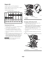
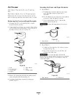
4. Loosen the outer nut on the spring eye bolt (Fig. 41)
enough to allow removal of the belt.
2
1
4
3
7
5
6
m–4197
Figure 41
Top View
1.
Outer nut
2.
Idler pulley
3.
Idler arm
4.
Spring eye bolt
5.
Spring
6.
9-3/8 in.
±
1/8 in.
(238 mm
±
3 mm)
7.
Mower belt
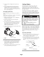
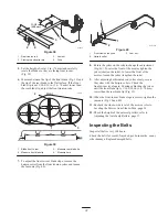
5. Remove the belt. Start at the outside pulley and rotate
the belt off (Fig. 42).
Note: Do not remove the spring.
The spring is under tension when installed and can
cause personal injury.
Do not remove the spring from the spring eye bolt.
Caution
6. Route the new belt through the idler arm (Fig. 41) and
onto the other pulleys (Fig. 42).
7. Tighten the outer nut on the spring eye bolt (Fig. 41).
Note: Check the spring length. The spring should measure
9-3/8 in.
±
1/8 in. (238 mm
±
3 mm) when installed with
the height-of-cut set at 1-1/2 in. (38 mm). Adjust it if it
does not (Fig. 41).
8. Install the belt covers over the outside spindles.
1
m–5157
2 3
4
5
Figure 42
Top View
1.
Mower belt
2.
Idler arm
3.
Outside pulley
4.
Spring
5.
Idler pulley
Removing the Mower
1. Park the machine on a level surface, disengage the PTO,
set the parking brake, stop the engine, and remove the
key. Disconnect the spark plug wire(s) from the spark
plug(s).
2. Lower the height-of-cut lever to the lowest position.
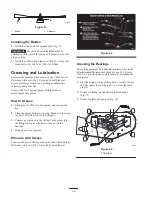
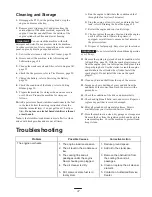
3. Remove the hairpin cotter and clevis pin from the front
trunion yokes (Fig. 43).
m–5178
1
2
Figure 43
1.
Hairpin cotter and clevis
pin
2.
Front trunion
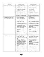
4. Remove the hairpin cotter and clevis pin from the rear
trunion rod (Fig. 44) on each side of the mower.
5. Remove the hairpin cotter and washer at the mower
leveling brackets (Fig. 44) on each side of the mower.
Note which hole the leveling bracket is mounted in for
future installation. Slide the brackets off of the
mounting pin.


