background image

During Operation

During Operation Safety

General Safety

The operator must use their full attention when
operating the machine.

Do Not

engage in any activity

that causes distractions; otherwise, injury or property
damage may occur.

WARNING

Operating engine parts, especially the muffler,
become extremely hot. Severe burns can
occur on contact and debris, such as leaves,
grass, brush, etc. can catch fire.

Allow engine parts, especially the muffler,
to cool before touching.

Remove accumulated debris from muffler
and engine area.

WARNING

Engine exhaust contains carbon monoxide,
which is an odorless deadly poison that can
kill you.

Do Not run engine indoors or in a small
confined area where dangerous carbon
monoxide fumes can collect.

The owner/user can prevent and is responsible
for accidents or injuries occurring to himself or
herself, other people or property.

This mower was designed for one operator only.
Do not carry passengers and keep all others away
from machine during operation.

Do Not operate the machine under the influence
of alcohol or drugs.

Operate only in daylight or good artificial light.

Lightning can cause severe injury or death. If
lightning is seen or thunder is heard in the area,
Do Not operate the machine; seek shelter.

Use extra care while operating with accessories or
attachments, such as grass collection systems.
These can change the stability of the machine
and cause a loss of control. Follow directions for
counter weights if required.

Keep away from holes, ruts, bumps, rocks, and
other hidden hazards. Use care when approaching
blind corners, shrubs, trees, tall grass or other
objects that may hide obstacles or obscure vision.
Uneven terrain could overturn the machine or
cause the operator to lose their balance or footing.

Be sure all drives are in neutral and parking brake
is engaged before starting engine.

Start the engine carefully according to instructions
with feet well away from the blades.

Never operate the mower with damaged guards,
shields, or covers. Always have safety shields,
guards, switches and other devices in place and in
proper working condition.

Keep clear of the discharge opening at all times.
Never mow with the discharge door raised,
removed or altered unless there is a grass
collection system or mulch kit in place and working
properly.

Keep hands and feet away from moving parts.
If possible, Do Not make adjustments with the
engine running.

WARNING

Hands, feet, hair, clothing, or accessories
can become entangled in rotating parts.
Contact with the rotating parts can
cause traumatic amputation or severe
lacerations.

– Do Not operate the machine without

guards, shields, and safety devices in
place and working properly.

– Keep hands, feet, hair, jewelry, or

clothing away from rotating parts.

Never raise the deck with blades running.

Be aware of the mower discharge path and direct
discharge away from others. Avoid discharging
material against a wall or obstruction as the
material may ricochet back toward the operator.
Stop the blades, slow down, and use caution when
crossing surfaces other than grass and when
transporting the mower to and from the area to be
mowed.

Be alert, slow down and use caution when
making turns. Look behind and to the side before
changing directions. Do Not mow in reverse
unless absolutely necessary.

Do Not change the engine governor setting or
overspeed the engine.

Park the machine on level ground. Stop engine,
wait for all moving parts to stop, and remove the
spark plug wire(s).

– Before checking, cleaning or working on the

mower.

– After striking a foreign object or abnormal

vibration occurs (inspect the mower for
damage and make repairs before restarting
and operating the mower).

– Before clearing blockages.

23


Summary of Contents for TimeCutter 74726

Page 1: ...4766 Serial No 404314200 and Up Model No 74766TA Serial No 400000000 and Up Model No 74768 Serial No 404314200 and Up Model No 74772 Serial No 404314000 and Up Model No 74773 Serial No 404314000 and Up Model No 74774 Serial No 404310000 and Up Model No 74774TA Serial No 400000000 and Up Model No 74777 Serial No 404314200 and Up Model No 74778 Serial No 404314200 and Up Register at www Toro com Ori...

Page 2: ...ltitudes otherwise you could overheat and damage the engine If you are unsure whether or not your machine has been converted for high altitude use look for the following label decal127 9363 Introduction This rotary blade riding lawn mower is intended to be used by homeowners in residential applications It is designed primarily for cutting grass on well maintained lawns Read this information carefu...

Page 3: ...he Machine by Hand 33 Maintenance 35 Recommended Maintenance Schedule s 35 Maintenance Safety 35 Pre Maintenance Procedures 37 Raising the Seat 37 Lubrication 37 Greasing the Bearings 37 Engine Maintenance 38 Engine Safety 38 Servicing the Air Cleaner 38 Servicing the Engine Oil 40 Servicing the Spark Plug 42 Cleaning the Cooling System 43 Fuel System Maintenance 43 Replacing the In Line Fuel Filt...

Page 4: ...hrowing objects Toro designed and tested this lawn mower to offer reasonably safe service however failure to comply with safety instructions may result in injury or death Read understand and follow all instructions and warnings in the Operator s Manual and other training material on the machine engine and attachments All operators and mechanics should be trained If the operator s or mechanic s can...

Page 5: ...rees Use the slope chart to determine the degree of slope of hills before operating Do not operate this machine on a slope greater than 15 degrees Fold along the appropriate line to match the recommended slope 2 Align this edge with a vertical surface a tree building fence pole etc 3 Example of how to compare slope with folded edge 5 ...

Page 6: ...ness or severe burns 4 Wear eye protection 9 Flush eyes immediately with water and get medical help fast 5 Read the Operator s Manual 10 Contains lead do not discard decaloemmarkt Manufacturer s Mark 1 Indicates the blade is identified as a part from the original machine manufacturer decal93 7009 93 7009 1 Warning do not operate the mower with the deflector up or removed keep the deflector in plac...

Page 7: ...for models with 152 cm 60 inch mower decks decal112 9840 112 9840 1 Read the Operator s Manual 3 Remove the ignition key and read the instructions before servicing or performing maintenance 2 Height of cut decal119 8814 119 8814 1 Parking position 4 Neutral 2 Fast 5 Reverse 3 Slow decal119 8815 119 8815 1 Parking position 4 Neutral 2 Fast 5 Reverse 3 Slow Decal 119 8870 is for is for models with 1...

Page 8: ...is for non MyRide models with 127 cm 50 inch 137 cm 54 inch or 152 cm 60 inch decks decal119 8871 119 8871 1 Height of cut 2 4 1 2 inches 3 4 inches 4 3 1 2 inches 5 3 inches 6 2 1 2 inches 7 2 inches 8 1 1 2 inches 8 ...

Page 9: ...decal121 0772 121 0772 1 Fast 4 Choke 2 Continuous variable setting 5 Power take off PTO Blade control switch 3 Slow 9 ...

Page 10: ...shing the machine 2 Bypass lever position for operating the machine decal131 1097 131 1097 1 Oil drain Decal 131 3947 does not apply to models without the MyRide suspension system or model 74773 decal131 3947 131 3947 1 Trim slow 3 Mow fast 2 Tow medium 10 ...

Page 11: ...s while operating on slopes can cause the machine to become unstable 1 Warning read the Operator s Manual 3 Cutting dismemberment hazard of the hand mower blade entanglement hazard of the hand belt stay away from moving parts keep all guards and shields in place 5 Ramp hazard do not use dual ramps when loading onto a trailer use 1 ramp wide enough for the machine use a ramp with a slope less than ...

Page 12: ...achine If possible keep the cutting units lowered to the ground while operating the machine on slopes Raising the cutting units while operating on slopes can cause the machine to become unstable 1 Warning read the Operator s Manual 5 Tipping hazard do not use on slopes near open water do not use on slopes greater than 15 2 Ramp hazard do not use dual ramps when loading onto a trailer use 1 ramp wi...

Page 13: ...2 Engine oil 5 Read the Operator s Manual before performing maintenance 3 Check the tire pressure every 25 operating hours Decal 136 9186 is for models with 152 cm 60 inch decks decal136 9186 136 9186 1 Read the Operator s Manual before adding weight to the bucket Decal 137 7044 is for models with the MyRide suspension system decal137 7044 137 7044 1 Cam lock 2 Cam unlock decal138 2456 138 2456 1 ...

Page 14: ...rottle control 3 Blade control switch power takeoff 2 Choke control 4 Key switch Key Switch The key switch used to start and shut off the engine has 3 positions OFF RUN and START Refer to Starting the Engine page 26 Throttle Control The throttle controls the engine speed and it has a continuous variable setting from the SLOW to FAST position Figure 6 Choke Control Use the choke control to start a ...

Page 15: ...eck from the seated position Moving the lever up toward you raises the deck from the ground and moving the lever down away from you lowers the deck toward the ground Adjust the height of cut only while the machine is not moving Figure 29 Hour Meter If Equipped The hour meter records the number of hours when you are in the seat and the key switch is in the ON position Figure 8 g027869 Figure 8 1 Th...

Page 16: ...y switches and shields are attached and functioning properly Do Not operate unless they are functioning properly Do Not operate the mower when people especially children or pets are in the area Stop the machine and attachment s if anyone enters the area Do Not operate the machine without the entire grass collection system discharge deflector or other safety devices in place and in proper working c...

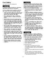
Page 17: ...ors A fire or explosion from gasoline can burn you and others and cause property damage Always place gasoline containers on the ground away from your vehicle before filling Do Not fill gasoline containers inside a vehicle or on a truck or trailer bed because interior carpets or plastic truck bed liners may insulate the container and slow the loss of any static charge When practical remove gas powe...

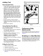
Page 18: ... stabilizer manufacturer Cleans the engine while it runs Eliminates gum like varnish buildup in the fuel system which causes hard starting Important Do not use fuel additives containing methanol or ethanol Add the correct amount of fuel stabilizer conditioner to the fuel Note A fuel stabilizer conditioner is most effective when mixed with fresh fuel To minimize the chance of varnish deposits in th...

Page 19: ...control levers in the PARK position and move the blade control switch to the ON position Try starting the engine the engine should not crank 2 Sit on the seat and move the blade control switch to the OFF position Move either motion control lever to the center unlocked position Try starting the engine the engine should not crank Repeat with the other motion control lever 3 Sit on the seat move the ...

Page 20: ...at where you have the best control of the machine and are most comfortable Figure 11 g265992 Figure 11 For Models 74772 and 74773 The seat can move forward and backward Position the seat where you have the best control of the machine and are most comfortable Figure 12 g265989 Figure 12 20 ...

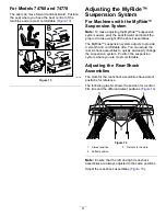
Page 21: ...justs to provide a smooth and comfortable ride You can adjust the rear 2 shock assemblies to quickly and easily change the suspension system Position the suspension system where you are most comfortable Adjusting the Rear Shock Assemblies The slots for the rear shock assemblies have detent positions for reference The following graphic shows the position for a soft or firm ride and the different de...

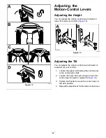
Page 22: ...usting the Tilt You can adjust the motion control levers forward or rearward for your comfort 1 Loosen the upper bolt holding the control lever to the control arm shaft 2 Loosen the lower bolt just enough to pivot the control lever forward or rearward Figure 16 3 Tighten both bolts to secure the control lever in the new position 4 Repeat the adjustment for the other control lever 22 ...

Page 23: ...or footing Be sure all drives are in neutral and parking brake is engaged before starting engine Start the engine carefully according to instructions with feet well away from the blades Never operate the mower with damaged guards shields or covers Always have safety shields guards switches and other devices in place and in proper working condition Keep clear of the discharge opening at all times N...

Page 24: ...e and good judgment when performing this evaluation Changes in the terrain such as moisture can quickly affect the operation of the machine on a slope Identify hazards at the base of the slope Do Not operate the machine near drop offs ditches embankments water or other hazards The machine could suddenly roll over if a wheel goes over the edge or the edge collapses Keep a safe distance twice the wi...

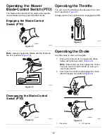
Page 25: ...0 Operating the Throttle You can move the throttle control between FAST and SLOW positions Figure 21 Always use the FAST position when engaging the PTO g187517 Figure 21 Operating the Choke Use the choke to start a cold engine 1 Pull up the choke knob to engage the choke before using the key switch Figure 22 Note Ensure that you fully engage the choke You may need to hold the knob up when you use ...

Page 26: ...ing the blade control switch to the OFF position Figure 23 2 Engage the parking brake refer to Park Position page 15 3 Move the throttle control to the FAST position 4 Turn the key to the OFF position and remove the key CAUTION Children or bystanders may be injured if they move or attempt to operate the machine while it is unattended Always remove the key and engage the parking brake when leaving ...

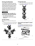
Page 27: ...y lose control of the machine and cause personal injury or damage to the machine Use caution when making turns Slow the machine down before making sharp turns Driving Forward Note Always use caution when backing up and turning 1 Move the levers to the center unlocked position 2 To go forward slowly push the motion control levers forward Figure 25 g008952 Figure 25 Driving Backward 1 Move the lever...

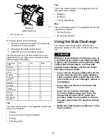
Page 28: ...chments Mow This is the fastest speed The suggested uses for this speed are as follows Normal mowing Moving the machine Using the Side Discharge The mower has a hinged grass deflector that disperses clippings to the side and down toward the turf DANGER Without a grass deflector discharge cover or a complete grass catcher assembly mounted in place you and others are exposed to blade contact and thr...

Page 29: ...LOCK position and engage the parking brake 2 Shut off the engine remove the key and wait for all moving parts to stop before leaving the operating position 3 Adjust the anti scalp rollers as shown in Figure 30 to match the closest height of cut position g010233 Figure 30 1 Anti scalp roller 3 Flange nut 2 Bolt 4 Hole spacing Machines with a 152 cm 60 inch Mower Deck Only Whenever you change the he...

Page 30: ...er than normal to ensure that the cutting height of the mower deck does not scalp any uneven ground However the cutting height used in the past is generally the best one to use When cutting grass longer than 15 cm 6 inches tall you may want to cut the lawn twice to ensure an acceptable quality of cut Cutting a Third of the Grass Blade It is best to cut only about a third of the grass blade Cutting...

Page 31: ...llow the machine to cool before adjusting cleaning repairing or storing Never allow untrained personnel to service machine Clean the machine as stated in the Maintenance section Keep engine and engine area free from accumulation of grass leaves excessive grease or oil and other debris which can accumulate in these areas These materials can become combustible and may result in a fire Frequently che...

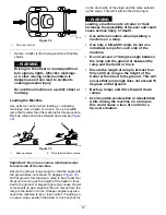
Page 32: ...the ground A steeper angle may cause mower components to get caught as the unit moves from the ramp to the trailer or truck Steeper angles may also cause the machine to tip or lose control If loading on or near a slope position the trailer or truck so that it is on the down side of the slope and the ramp extends up the slope This will minimize the ramp angle WARNING Loading a machine onto a traile...

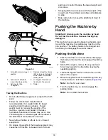
Page 33: ...d loss of control Reduce the towed weight and slow down Stopping distance increases with the weight of the towed load Travel slowly and allow extra distance to stop Make wide turns to keep the attachment clear of the machine Pushing the Machine by Hand Important Always push the machine by hand Do not tow the machine because towing may damage it This machine has an electric brake mechanism and to p...

Page 34: ...e STOP position to avoid draining the battery charge Note If the machine fails to move the electric brake may still be engaged You can release the electric brake manually if necessary refer to Releasing the Electric Brake page 47 Operating the Machine Move the bypass levers rearward through the keyhole and down to lock them in place as shown in Figure 35 Note Do this for each lever 34 ...

Page 35: ...g s Check the in line fuel filter Every 200 hours Replace the paper air cleaner element more often in dirty or dusty conditions Replace the spark plug s Replace the in line fuel filter Before storage Charge the battery and disconnect the battery cables Perform all maintenance procedures listed above before storage Paint any chipped surfaces CAUTION If you leave the key in the switch someone could ...

Page 36: ... violate applicable safety standards such as ANSI OSHA and NFPA and or government regulations such as EPA and CARB Use care when checking blades Wrap the blade s or wear gloves and use caution when servicing them Only replace damaged blades Never straighten or weld them Use jack stands to support the machine and or components when required CAUTION Raising the machine for service or maintenance rel...

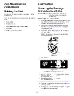
Page 37: ...levers to the NEUTRAL LOCK position and engage the parking brake 2 Shut off the engine remove the key and wait for all moving parts to stop before leaving the operating position 3 Clean the grease fittings Figure 36 and Figure 37 with a rag Note Make sure to scrape any paint off the front of the fitting s g032432 Figure 36 1 Front caster tire decal106 8717 Figure 37 Located on the seat pan undersi...

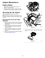
Page 38: ...e extremely dusty or sandy Removing the Foam and Paper Elements 1 Park the machine on a level surface disengage the blade control switch PTO and engage the parking brake 2 Shut off the engine remove the key and wait for all moving parts to stop before leaving the operating position 3 Clean around the air cleaner cover to prevent dirt from getting into the engine and causing damage 4 Lift the cover...

Page 39: ...urs Clean the paper air cleaner element more often in dirty or dusty conditions Every 200 hours Replace the paper air cleaner element more often in dirty or dusty conditions 1 Clean the paper element by tapping it gently to remove dust Note If it is very dirty replace the paper element with a new one 2 Inspect the element for tears an oily film or damage to the rubber seal 3 Replace the paper elem...

Page 40: ...perating position Note Ensure that the engine is cool so that the oil has had time to drain into the sump 3 To keep dirt grass clippings etc out of the engine clean the area around the oil fill cap and dipstick before removing it Figure 42 g193541 Figure 42 Changing the Engine Oil and Oil Filter Service Interval After the first 5 hours After the first month whichever comes first Change the engine ...

Page 41: ... Note Ensure that the oil filter gasket touches the engine and then turn the filter an extra 3 4 turn g027477 Figure 44 6 Slowly pour approximately 80 of the specified oil into the filler tube and slowly add the additional oil to bring it to the Full mark Figure 45 41 ...

Page 42: ...ap 0 76 mm 0 03 inch Removing the Spark Plug 1 Park the machine on a level surface disengage the blade control switch PTO and engage the parking brake 2 Shut off the engine remove the key and wait for all moving parts to stop before leaving the operating position 3 Clean the area around the base of the plug to keep dirt and debris out of the engine 4 Remove the spark plug Figure 46 g027478 Figure ...

Page 43: ...lter Fuel System Maintenance DANGER In certain conditions fuel is extremely flammable and highly explosive A fire or explosion from fuel can burn you and others and can damage property Refer to Adding Fuel page 18 for a complete list of fuel related precautions Replacing the In Line Fuel Filter Service Interval Every 100 hours Yearly whichever comes first Check the in line fuel filter Every 200 ho...

Page 44: ...etal tools could short against metal machine components causing sparks Sparks can cause the battery gasses to explode resulting in personal injury When removing or installing the battery do not allow the battery terminals to touch any metal parts of the machine Do not allow metal tools to short between the battery terminals and metal parts of the machine 1 Park the machine on a level surface disen...

Page 45: ... Charging the Battery Service Interval Before storage Charge the battery and disconnect the battery cables 1 Remove the battery from the chassis refer to Removing the Battery page 44 2 Charge the battery for a minimum of 1 hour at 6 to 10 A Note Do not overcharge the battery 3 When the battery is fully charged unplug the charger from the electrical outlet then disconnect the charger leads from the...

Page 46: ...osition Note Use the screws removed previously to secure the panel to the machine Drive System Maintenance Checking the Tire Pressure Service Interval Every 25 hours Check tire pressure Maintain the air pressure in the front and rear tires as specified Uneven tire pressure can cause uneven cut Check the pressure at the valve stem Figure 53 Check the tires when they are cold to get the most accurat...

Page 47: ...ng grass and frayed edges burn marks and cracks on the belt Replace the mower belt if any of these conditions are evident 1 Park the machine on a level surface disengage the blade control switch PTO and engage the parking brake 2 Shut off the engine remove the key and wait for all moving parts to stop before leaving the operating position 3 Set the height of cut at the lowest cutting position of 3...

Page 48: ...ks with 3 Blades 1 Idler pulley 4 Spring 2 Mower belt 5 Engine pulley 3 Outside pulley 6 Spring removal tool 6 Route the new belt around the engine pulley and mower pulleys Figure 57 7 Using a spring removal tool install the idler spring over the deck hook and place tension on the idler pulley and mower belt Figure 56 and Figure 57 8 Install the pulley covers 48 ...

Page 49: ...gage the parking brake 2 Shut off the engine remove the key and disconnect the spark plug wires from the spark plugs Inspecting the Blades Service Interval Before each use or daily 1 Inspect the cutting edges Figure 58 2 If the edges are not sharp or have nicks remove and sharpen the blade refer to Sharpening the Blades page 51 3 Inspect the blades especially in the curved area 4 If you notice any...

Page 50: ... surface 3 Second measured distance between blade and surface B A If the difference between A and B is greater than 3 mm 1 8 inch replace the blade with a new blade refer to Removing the Blades page 50 and Installing the Blades page 51 Note If a bent blade is replaced with a new blade and the dimension obtained continues to exceed 3 mm 1 8 inch the blade spindle could be bent Contact an Authorized...

Page 51: ...wer to ensure proper cutting 2 Install the curved washer cupped side toward the blade and the blade bolt Figure 63 3 Torque the blade bolt to 47 to 88 N m 35 to 65 ft lb Leveling the Mower Deck Check to ensure that the mower deck is level any time you install the mower or when you see an uneven cut on your lawn Check the mower deck for bent blades prior to leveling and remove and replace any bent ...

Page 52: ...7588 Figure 68 1 Hanger bracket 3 Rear nut 2 Side locking nut 9 Check the side to side adjustments again Repeat this procedure until the measurements are correct 10 Continue leveling the mower deck by checking the front to rear blade slope refer to Adjusting the Front to Rear Blade Slope page 52 Adjusting the Front to Rear Blade Slope Check the front to rear blade level any time you install the mo...

Page 53: ...6 to 7 9 mm 1 16 to 5 16 inch lower than the rear blade tip Figure 69 and Figure 70 g014634 Figure 71 1 Adjusting rod 3 Locknut 2 Adjusting block 7 For 60 inch mower decks adjust the front to rear blade slope as follows A Loosen the adjustment nut on the left adjusting rod Figure 70 B To raise the front of the mower tighten the adjustment nut on the right adjusting rod C To lower the front of the ...

Page 54: ...rts for future installation Installing the Mower 1 Park the machine on a level surface disengage the blade control switch PTO and engage the parking brake 2 Shut off the engine remove the key and wait for all moving parts to stop before leaving the operating position 3 Slide the mower under the machine 4 Lower the height of cut lever to the lowest position 5 Lift the rear of the mower deck and gui...

Page 55: ...ector bracket and slide the rod out of the welded deck brackets spring and discharge deflector Figure 75 g017617 Figure 75 1 Rod 4 Deck brackets 2 Spring 5 Spring installed over the rod 3 Deflector 2 Remove the damaged or worn discharge deflector 3 Position the new discharge deflector with the bracket ends between the welded brackets on the deck as shown in Figure 76 4 Install the spring onto the ...

Page 56: ...ection system in place Inspect the grass deflector for damage before each use Replace any damaged parts before use 1 Remove the nut 3 8 inch from the rod under the mower Figure 77 g005192 Figure 77 1 Mower deck 5 Spring 2 Grass deflector 6 Nut 3 8 inch 3 Grass deflector bracket 7 Short standoff 4 Rod 2 Slide the rod out of the short standoff the spring and the grass deflector Figure 77 3 Remove th...

Page 57: ...4 Coupling 4 Lower the mower to the lowest height of cut 5 Sit on the seat and start the engine 6 Engage the blade control switch and let the mower run for 1 to 3 minutes 7 Disengage the blade control switch shut off the engine remove the key and wait for all moving parts to stop 8 Turn the water off and remove the coupling from the washout fitting Note If the mower is not clean after 1 washing so...

Page 58: ...or 2 to 5 minutes after washing 11 Check the condition of the blades refer to Inspecting the Blades page 49 12 Prepare the machine for storage when non use occurs over 30 days Prepare the machine for storage as follows A Add a petroleum based stabilizer conditioner to fuel in the tank Follow mixing instructions from the stabilizer manufacturer Do not use an alcohol based stabilizer ethanol or meth...

Page 59: ... that the voltage is 12 4 V or higher Note If the battery voltage is below 12 4 V repeat steps 1 and 2 Battery Storage Tips Store the battery in a cool dry area in an upright position Do not stack batteries directly on top of each other unless they are in cartons Do not stack more than 3 batteries only 2 if the battery type is commercial Test a wet battery every 4 to 6 months and charge it if nece...

Page 60: ...ed spark plug s 5 There is dirt in fuel filter 5 Replace the fuel filter 6 Dirt water or stale fuel is in fuel system 6 Contact an Authorized Service Dealer 7 There is incorrect fuel in the fuel tank 7 Drain the tank and replace the fuel with the proper type The engine does not start starts hard or fails to keep running 8 The oil level in the crankcase is low 8 Add oil to the crankcase 1 The engin...

Page 61: ...nstall a new cutting blade s 3 The mower is not level 3 Level the mower from side to side and front to rear 4 An anti scalp wheel is not set correctly 4 Adjust the anti scalp wheel height 5 The underside of the mower is dirty 5 Clean the underside of the mower 6 The tire pressure is incorrect 6 Adjust the tire pressure The cutting height is uneven 7 A blade spindle is bent 7 Contact an Authorized ...

Page 62: ...Schematics g028022 Electrical Diagram Rev A 62 ...

Page 63: ...Notes ...

Page 64: ......

Reviews: