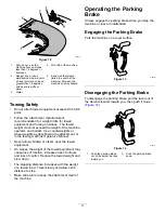
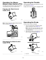
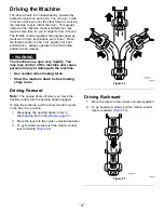
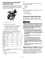
background image

9.

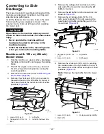
Locate the cutoff baffle in the loose parts bag
and remove the fasteners at the rear holes of
the discharge plate (

Figure 31

).

g190734

Figure 31

1.

Carriage bolts (existing)

3.

Cutoff baffle (loose)

2.

Rear holes in the
discharge plate

4.

Locknuts (existing)

10.

Install the baffle at the side discharge opening
on the mower deck.

11.

Use the fasteners removed to secure the cutoff
baffle to the deck.

12.

Install the mower deck; refer to

Installing the

Mower Deck (page 47)

.

Machines with 137 cm (54-inch)
Mower Decks

1.

Park the machine on a level surface, disengage
the blade-control switch, and engage the parking
brake.

2.

Shut off the engine, remove the key, and wait
for all moving parts to stop before leaving the
operating position.

3.

Remove the mower deck; refer to

Removing the

Mower Deck (page 46)

.

4.

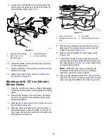
Remove the 3 locknuts (5/16 inch) secured to
the welded posts of the left baffle on the top of
the mower deck at the center, left of center, and
left positions (

Figure 32

).

g011149

Figure 32

1.

Locknut (5/16 inch)

3.

Left baffle

2.

Carriage bolt (5/16 x 3/4
inch)

4.

Install the fasteners here.

5.

Remove the carriage bolt and locknut on the
side wall of the mower deck securing the left
baffle to the deck (

Figure 32

).

6.

Remove the left baffle from the mower deck
(

Figure 32

).

7.

Locate the 2 bolts in loose parts and use the
existing locknuts and install these fasteners into
the holes shown in

Figure 32

on the mower deck

to prevent flying debris.

Note:

Install the bolt upward, through the

underside of the deck and use an existing
locknut to secure from the topside.

8.

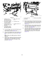
Remove the carriage bolt (5/16 x 3/4 inch) and
locknut (5/16 inch) on the rear wall of the mower
deck securing the baffle to the deck (

Figure 33

).

24


Summary of Contents for TimeCutter HD X4850

Page 1: ... No 3419 548 Rev A TimeCutter HD X4850 and X5450 Riding Mower Model No 74864 Serial No 402000000 and Up Model No 74865 Serial No 402000000 and Up Register at www Toro com Original Instructions EN 3419 548 A ...

Page 2: ...tact our Toro Customer Care Department at the number s listed in your Emission Control Warranty Statement Remove the kit from the engine and restore the engine to its original factory configuration when running the engine under 1500 m 5 000 ft Do not operate an engine that has been converted for high altitude use at lower altitudes otherwise you could overheat and damage the engine If you are unsu...

Page 3: ...on 15 During Operation Safety 15 Operating the Parking Brake 17 Operating the Mower Blade Control Switch PTO 18 Operating the Throttle 18 Operating the Choke 18 Starting the Engine 19 Shutting Off the Engine 19 Using the Motion Control Levers 19 Driving the Machine 20 Using the Smart SpeedTM Control System 21 Using the Side Discharge 21 Adjusting the Height of Cut 21 Adjusting the Anti Scalp Rolle...

Page 4: ...machine near drop offs ditches embankments water or other hazards or on slopes greater than 15 degrees Read and understand the contents of this Operator s Manual before starting the engine Do not put your hands or feet near moving components of the machine Do not operate the machine without all guards and other safety protective devices in place and working on the machine Keep children and bystand...

Page 5: ...rees Use the slope chart to determine the degree of slope of hills before operating Do not operate this machine on a slope greater than 15 degrees Fold along the appropriate line to match the recommended slope 2 Align this edge with a vertical surface a tree building fence pole etc 3 Example of how to compare slope with folded edge 5 ...

Page 6: ...your battery 1 Explosion hazard 6 Keep bystanders a safe distance away from the battery 2 No fire open flame or smoking 7 Wear eye protection explosive gases can cause blindness and other injuries 3 Caustic liquid chemical burn hazard 8 Battery acid can cause blindness or severe burns 4 Wear eye protection 9 Flush eyes immediately with water and get medical help fast 5 Read the Operator s Manual 1...

Page 7: ...itch and read the Operator s Manual before performing maintenance 2 Height of cut selection decal131 1097 131 1097 1 Oil drain 131 3948 decal131 3948 131 3948 1 Slow 3 Fast 2 Towing decal132 0872 132 0872 1 Thrown object hazard keep bystanders away from the machine 3 Severing hazard of hand or foot keep away from moving parts 2 Thrown object hazard raised baffle do not operate the machine with an ...

Page 8: ...Slow 4 Reverse decal136 5596 136 5596 1 Check the tire pressure every 25 operating hours 4 Check the tire pressure every 25 operating hours 2 Engine oil 5 Read the Operator s Manual before performing maintenance 3 Check the tire pressure every 25 operating hours decal136 9186 136 9186 1 Read the Operator s Manual before adding weight to the bucket 8 ...

Page 9: ...ecome unstable 1 Warning read the Operator s Manual 5 Tipping hazard do not use on slopes near open water do not use on slopes greater than 15 2 Ramp hazard do not use dual ramps when loading onto a trailer use 1 ramp wide enough for the machine use a ramp with a slope less than 15 back up the ramp when loading the machine and drive forward off the ramp when unloading 6 Cutting and pinch hazard ke...

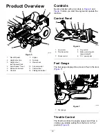
Page 10: ...th all controls in Figure 6 and Figure 7 before you start the engine and operate the machine Control Panel g188738 Figure 6 1 Hour meter 4 Key switch 2 Throttle control 5 Blade control switch power takeoff 3 Choke control 6 12 V power point Fuel Gauge The fuel gauge displays the amount of fuel in the tank Figure 7 g188776 Figure 7 1 Fuel gauge Throttle Control The throttle controls the engine spee...

Page 11: ...e 5 Smart Speed Control System Lever The Smart Speed Control System lever located below the operating position gives you a choice to drive the machine at 3 speed ranges trim tow and mow Figure 5 12 V Power Point Use the power point to power 12 V accessories Figure 6 Important When not using the 12 V power point insert the rubber plug to prevent damage to the power point Key Switch The key switch u...

Page 12: ...ay from your vehicle before filling Remove the equipment from the truck or trailer and refuel it while it is on the ground If this is not possible then refuel from a portable container rather than a fuel dispenser nozzle Do not operate the machine without the entire exhaust system in place and in proper working condition Keep the fuel dispenser nozzle in contact with the rim of the fuel tank or co...

Page 13: ...the fuel system use fuel stabilizer at all times Filling the Fuel Tank 1 Park the machine on a level surface 2 Engage the parking brake 3 Shut off the engine and remove the key 4 Clean around the fuel tank cap 5 Fill the fuel tank until the fuel gauge reads at the full mark Figure 8 Note Do not fill the fuel tank completely full The empty space in the tank allows the fuel to expand g197123 Figure ...

Page 14: ...ngine the engine should not crank 2 Sit on the seat engage the parking brake and move the blade control switch PTO to the OFF position Move either motion control lever out of the NEUTRAL LOCK position Try starting the engine the engine should not crank Repeat for other control lever 3 Sit on the seat engage the parking brake move the blade control switch PTO to the OFF position and move the motion...

Page 15: ...the machine only in good visibility to avoid holes or hidden hazards Avoid mowing on wet grass Reduced traction could cause the machine to slide Ensure that all drives are in neutral the parking brake is engaged and you are in the operating position before you start the engine Keep your hands and feet away from the cutting units Keep clear of the discharge opening at all times Look behind and down...

Page 16: ... on a slope Identify hazards at the base of the slope Do not operate the machine near drop offs ditches embankments water or other hazards The machine could suddenly roll over if a wheel goes over the edge or the edge collapses Keep a safe distance twice the width of the machine between the machine and any hazard Use a walk behind machine or a hand trimmer to mow the grass in these areas Avoid sta...

Page 17: ...r in the towing machine Operator s Manual Never allow children or others near the towed equipment On slopes the weight of the towed equipment may cause loss of traction increased risk of rollover and loss of control Reduce the towed weight and slow down The stopping distance increases with the weight of a towed load Travel slowly and allow extra distance to stop Make wide turns to keep the attachm...

Page 18: ...7 Operating the Throttle You can move the throttle control between FAST and SLOW positions Figure 18 Always use the FAST position when engaging the PTO g187517 Figure 18 Operating the Choke Use the choke to start a cold engine 1 Pull up the choke knob to engage the choke before using the key switch Figure 19 Note Ensure that you fully engage the choke You may need to hold the knob up when you use ...

Page 19: ...itch to the OFF position Figure 19 2 Engage the parking brake refer to Engaging the Parking Brake page 17 3 Move the throttle control to the FAST position 4 Turn the key to the OFF position and remove the key CAUTION Children or bystanders may be injured if they move or attempt to operate the machine while it is unattended Always remove the key and engage the parking brake when leaving the machine...

Page 20: ...e can spin very rapidly You may lose control of the machine and cause personal injury or damage to the machine Use caution when making turns Slow the machine down before making sharp turns Driving Forward Note The engine shuts off when you move the traction control with the parking brake engaged To stop the machine pull the motion control levers to the NEUTRAL position 1 Disengage the parking brak...

Page 21: ...owing Moving the machine Using the Side Discharge The mower has a hinged grass deflector that disperses clippings to the side and down toward the turf DANGER Without a grass deflector discharge cover or a complete grass catcher assembly mounted in place you and others are exposed to blade contact and thrown debris Contact with rotating mower blade s and thrown debris will cause injury or death Nev...

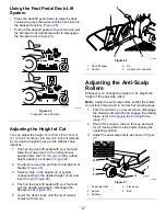
Page 22: ...ct a hole in the height of cut system corresponding to the desired height of cut and insert the pin Figure 26 4 Push on the deck lift pedal with your foot and pull the handle rearward to disengage the transport lock Figure 25 5 Lower the deck slowly until the lever makes contact with the pin g188850 Figure 26 1 Deck lift pedal 3 Pin 2 Handle 4 Height of cut positions Adjusting the Anti Scalp Rolle...

Page 23: ...mower deck refer to Removing the Mower Deck page 46 4 Remove the 2 locknuts 5 16 inch secured to the welded posts of the left baffle on the top of the mower deck at the center and left of center positions Figure 28 g011149 Figure 28 1 Locknut 5 16 inch 3 Left baffle 2 Carriage bolt 5 16 x 3 4 inch 4 Install the fasteners here 5 Remove the carriage bolt and locknut on the side wall of the mower dec...

Page 24: ...ck refer to Removing the Mower Deck page 46 4 Remove the 3 locknuts 5 16 inch secured to the welded posts of the left baffle on the top of the mower deck at the center left of center and left positions Figure 32 g011149 Figure 32 1 Locknut 5 16 inch 3 Left baffle 2 Carriage bolt 5 16 x 3 4 inch 4 Install the fasteners here 5 Remove the carriage bolt and locknut on the side wall of the mower deck s...

Page 25: ...te Remove the baffle guard and retain all fasteners 11 Remove the 2 locknuts 5 16 inch securing the welded posts of the right baffle to the top of the mower deck at center and right of center positions Figure 34 g010704 Figure 34 1 Locknut 5 16 inch 3 Welded posts right baffle 2 Right baffle 12 Remove the carriage bolt and locknut securing the right baffle to the top of the mower deck and remove t...

Page 26: ...n for the First Time Cut grass slightly longer than normal to ensure that the cutting height of the mower deck does not scalp any uneven ground However the cutting height used in the past is generally the best one to use When cutting grass longer than 15 cm 6 inches tall you may want to cut the lawn twice to ensure an acceptable quality of cut Cutting a Third of the Grass Blade It is best to cut o...

Page 27: ...s Clean up oil or fuel spills Shut off the fuel before storing or transporting the machine Disengage the drive to the attachment whenever you are transporting or not using the machine Allow the engine to cool before storing the machine in any enclosure Never store the machine or fuel container where there is an open flame spark or pilot light such as on a water heater or on other appliances Pushin...

Page 28: ...p you or bystanders avoid injury Refer to your local ordinances for trailer and tie down requirements WARNING Driving on the street or roadway without turn signals lights reflective markings or a slow moving vehicle emblem is dangerous and can lead to accidents causing personal injury Do not drive the machine on a public street or roadway Selecting a Trailer WARNING Loading a machine onto a traile...

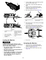
Page 29: ...ontrol or a tip over situation 1 If using a trailer connect it to the towing vehicle and connect the safety chains 2 If applicable connect the trailer brakes and lights 3 Lower the ramp ensuring that the angle between the ramp and the ground does not exceed 15 degrees Figure 37 4 Back the machine up the ramp Figure 38 g027995 Figure 38 1 Back the machine up the ramp 2 Drive the machine forward dow...

Page 30: ...he belts for wear or cracks Every 100 hours Replace the air cleaner foam element more often in dusty dirty conditions Clean the paper air cleaner element more often in dirty or dusty conditions Change the engine oil and oil filter more often in dirty or dusty conditions Check the spark plug s Check the in line fuel filter Every 200 hours Replace the paper air cleaner element more often in dirty or...

Page 31: ...tion when servicing them Only replace blades do not straighten or weld them Keep your hands and feet away from moving parts If possible do not make adjustments with the engine running Keep all parts in good working condition and all hardware tightened especially the blade attachment bolts Replace all worn or damaged decals Never interfere with the intended function of a safety device or reduce the...

Page 32: ...e extremely dusty or sandy Removing the Foam and Paper Elements 1 Park the machine on a level surface disengage the blade control switch PTO and engage the parking brake 2 Shut off the engine remove the key and wait for all moving parts to stop before leaving the operating position 3 Clean around the air cleaner cover to prevent dirt from getting into the engine and causing damage 4 Lift the cover...

Page 33: ...ce the paper air cleaner element more often in dirty or dusty conditions 1 Clean the paper element by tapping it gently to remove dust Note If it is very dirty replace the paper element with a new one 2 Inspect the element for tears an oily film or damage to the rubber seal 3 Replace the paper element if it is damaged Important Do not clean the paper filter Installing the Air Cleaner 1 Install the...

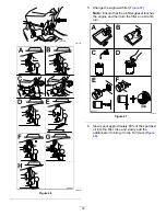
Page 34: ...sump 3 To keep dirt grass clippings etc out of the engine clean the area around the oil fill cap and dipstick before removing it Figure 45 g235263 Figure 45 Changing the Engine Oil and Oil Filter Service Interval After the first 5 hours After the first month whichever comes first Change the engine oil and filter Every 100 hours Yearly whichever comes first Change the engine oil and oil filter more...

Page 35: ... Note Ensure that the oil filter gasket touches the engine and then turn the filter an extra 3 4 turn g027477 Figure 47 6 Slowly pour approximately 80 of the specified oil into the filler tube and slowly add the additional oil to bring it to the Full mark Figure 48 35 ...

Page 36: ...emoving the Spark Plug 1 Park the machine on a level surface disengage the blade control switch PTO and engage the parking brake 2 Shut off the engine remove the key and wait for all moving parts to stop before leaving the operating position 3 Clean the area around the base of the plug to keep dirt and debris out of the engine 4 Remove the spark plug Figure 49 g027478 Figure 49 Checking the Spark ...

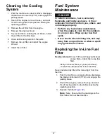
Page 37: ...hers and can damage property Perform any fuel related maintenance when the engine is cold Do this outdoors in an open area Wipe up any fuel that spills Never smoke when draining fuel and stay away from an open flame or where a spark may ignite the fuel fumes Replacing the In Line Fuel Filter Service Interval Every 100 hours Yearly whichever comes first Check the in line fuel filter Every 200 hours...

Page 38: ...NING Incorrectly removing the cables from battery could damage the machine and cables causing sparks Sparks can cause the battery gasses to explode resulting in personal injury Always disconnect the negative black battery cable before disconnecting the positive red cable Always connect the positive red battery cable before connecting the negative black cable 1 Park the machine on a level surface d...

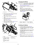
Page 39: ... battery from the chassis refer to Removing the Battery page 38 2 Charge the battery for a minimum of 1 hour at 6 to 10 A Note Do not overcharge the battery 3 When the battery is fully charged unplug the charger from the electrical outlet then disconnect the charger leads from the battery posts Figure 55 g000538 Figure 55 1 Positive battery post 3 Red charger lead 2 Negative battery post 4 Black c...

Page 40: ...of battery pull out the fuse and install a new 25 A fuse Figure 57 g190589 Figure 57 1 Charge circuit 25 A Drive System Maintenance Checking the Tire Pressure Service Interval Every 25 hours Check tire pressure Maintain the air pressure in the front and rear tires as specified Uneven tire pressure can cause uneven cut Check the pressure at the valve stem Figure 58 Check the tires when they are col...

Page 41: ...ccess the idler pulley 8 Using a spring removal tool Toro Part No 92 5771 remove the idler spring from the deck post to remove tension on the idler pulley Figure 59 g009806 Figure 59 1 Spring removal tool Toro Part No 92 5771 4 Idler arm 2 Idler spring 5 Mower belt 3 Deck post 9 Lower the mower to the lowest height of cut and place the height of cut pin in the lock position for the lowest height o...

Page 42: ...gage the parking brake 2 Shut off the engine remove the key and disconnect the spark plug wires from the spark plugs Inspecting the Blades Service Interval Before each use or daily 1 Inspect the cutting edges Figure 60 2 If the edges are not sharp or have nicks remove and sharpen the blade refer to Sharpening the Blades page 44 3 Inspect the blades especially in the curved area 4 If you notice any...

Page 43: ...The variance should be no more than 3 mm 1 8 inch g014973 Figure 64 1 Opposite blade edge in position for measuring 2 Level surface 3 Second measured distance between blade and surface B A If the difference between A and B is greater than 3 mm 1 8 inch replace the blade with a new blade refer to Removing the Blades page 44 and Installing the Blades page 44 Note If a bent blade is replaced with a n...

Page 44: ... at original angle 2 Check the balance of the blade by putting it on a blade balancer Figure 67 Note If the blade stays in a horizontal position the blade is balanced and can be used Note If the blade is not balanced file some metal off the end of the sail area only Figure 66 g000553 Figure 67 1 Blade 2 Balancer 3 Repeat this procedure until the blade is balanced Installing the Blades 1 Install th...

Page 45: ...in 5 mm 3 16 inch an adjustment is required refer to Leveling the Mower Deck page 46 g229303 Figure 69 1 Blades side to side 3 Measure from the tip of the blade to the flat surface here 2 Outside cutting edges Checking the Front to Rear Blade Slope Check the front to rear blade level any time you install the mower If the front of the mower is more than 7 9 mm 5 16 inch lower than the rear of the m...

Page 46: ...13 Figure 72 1 Deck lift arm 3 Hook 2 Chain 4 Adjustment bolt 6 Ensure that there is tension on all 4 chains Figure 72 7 Tighten the 4 adjustment bolts Figure 72 8 Ensure that the blocks fit snugly under the deck skirt and that all bolts are tight 9 Verify that the deck is level by checking the side to side level and front to rear blade slope repeat the deck leveling procedure if necessary Removin...

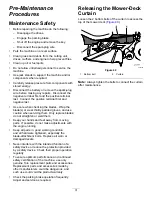
Page 47: ...rake 2 Shut off the engine remove the key and disconnect the spark plug wires from the spark plugs 3 Slide the mower under the machine 4 Lower the height of cut lever to the lowest position 5 Place the height of cut pin in the lock position for lowest height of cut 6 Lift the rear of the mower deck and attach the chains to the rear lift arms Figure 74 7 Attach the front chains to the front lift ar...

Page 48: ... discharge deflector 4 Position the new discharge deflector with the bracket ends between the welded brackets on the deck as shown in Figure 76 5 Install the spring onto the straight end of the rod 6 Position the spring on the rod as shown in Figure 76 so the shorter spring end is coming from under the rod before the bend and going over the rod as it returns from the bend 7 Lift the loop end of th...

Page 49: ... on 54 inch decks 4 O ring 2 Washout fitting locations on 48 inch decks 5 Hose 3 Washout fitting 4 Lower the mower to the lowest height of cut 5 Sit on the seat and start the engine 6 Engage the blade control switch and let the mower run for 1 to 3 minutes 7 Disengage the blade control switch PTO shut off the engine remove the key from the key switch and wait for all moving parts to stop 8 Turn th...

Page 50: ...ng 10 Check the condition of the blades refer to Servicing the Cutting Blades page 42 11 Prepare the machine for storage when non use occurs over 30 days Prepare the machine for storage as follows A Add a petroleum based stabilizer conditioner to fuel in the tank Follow mixing instructions from the stabilizer manufacturer Do not use an alcohol based stabilizer ethanol or methanol Note A fuel stabi...

Page 51: ... that the voltage is 12 4 V or higher Note If the battery voltage is below 12 4 V repeat steps 1 and 2 Battery Storage Tips Store the battery in a cool dry area in an upright position Do not stack batteries directly on top of each other unless they are in cartons Do not stack more than 3 batteries only 2 if the battery type is commercial Test a wet battery every 4 to 6 months and charge it if nece...

Page 52: ...Move the choke lever to the ON position 3 The air cleaner is dirty 3 Clean or replace the air cleaner element 4 The spark plug wire s is loose or disconnected 4 Install the wire s on the spark plug 5 The spark plug s is pitted fouled or the gap is incorrect 5 Install a new correctly gapped spark plug s 6 There is dirt in fuel filter 6 Replace the fuel filter 7 Dirt water or stale fuel is in fuel s...

Page 53: ...ne vibrates abnormally 7 The motor mount is loose or worn 7 Contact an Authorized Service Dealer 1 The blade s is not sharp 1 Sharpen the blade s 2 A cutting blade s is are bent 2 Install a new cutting blade s 3 The mower is not level 3 Level the mower from side to side and front to rear 4 An anti scalp roller if applicable is not set correctly 4 Adjust the anti scalp wheel height 5 The underside ...

Page 54: ...Schematics g203461 Electrical Diagram Rev A 54 ...

Page 55: ...Notes ...

Page 56: ...f these activities We will not sell your personal information to any other company We reserve the right to disclose personal information in order to comply with applicable laws and with requests by the appropriate authorities to operate our systems properly or for our own protection or that of other users Retention of your Personal Information We will keep your personal information as long as we n...

Reviews: