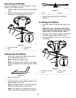
g028276
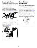
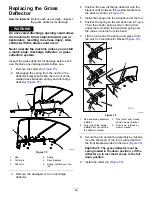
Figure 73
1.
Link pin
3.
Hairpin cotter
2.
Washer
7.
Lift up the mower deck to relieve tension from
the mower deck.
8.
Remove the chains from the hooks on the
deck-lift arms (
).
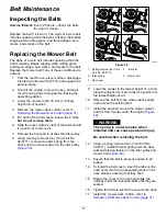
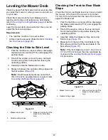
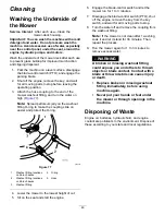
g024313
Figure 74
1.
Deck-lift arm
3.
Hook
2.
Chain
4.
Adjustment bolt
9.
Raise the height of cut to the transport position.
10.
Remove the belt from the clutch pulley on the
engine.
11.
Slide the mower out from underneath the
machine.
Note:
Retain all parts for future installation.
Installing the Mower Deck
1.
Park the machine on a level surface, disengage
the blade-control switch (PTO), and engage the
parking brake.
2.
Shut off the engine, remove the key, and
disconnect the spark-plug wires from the spark
plugs.
3.
Slide the mower under the machine.
4.
Lower the height-of-cut lever to the lowest
position.
5.
Place the height-of-cut pin in the lock position
for lowest height of cut.
6.
Lift the rear of the mower deck and attach the
chains to the rear lift arms (
).
7.
Attach the front chains to the front lift arms
(
).
8.
Install the long link bar through the frame hanger
and deck.
9.
Secure the link pin with the hairpin cotters and
washers removed previously (
10.
Install the mower belt onto the engine pulley;
refer to
Installing the Mower Deck (page 47)
.
11.
Tighten the 2 bottom bolts holding the
mower-deck curtain to the mower deck; refer to
Releasing the Mower-Deck Curtain (page 31)
.
47
Summary of Contents for TimeCutter HD X4850
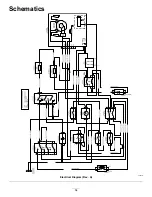
Page 54: ...Schematics g203461 Electrical Diagram Rev A 54 ...
Page 55: ...Notes ...


