6.
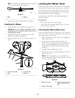
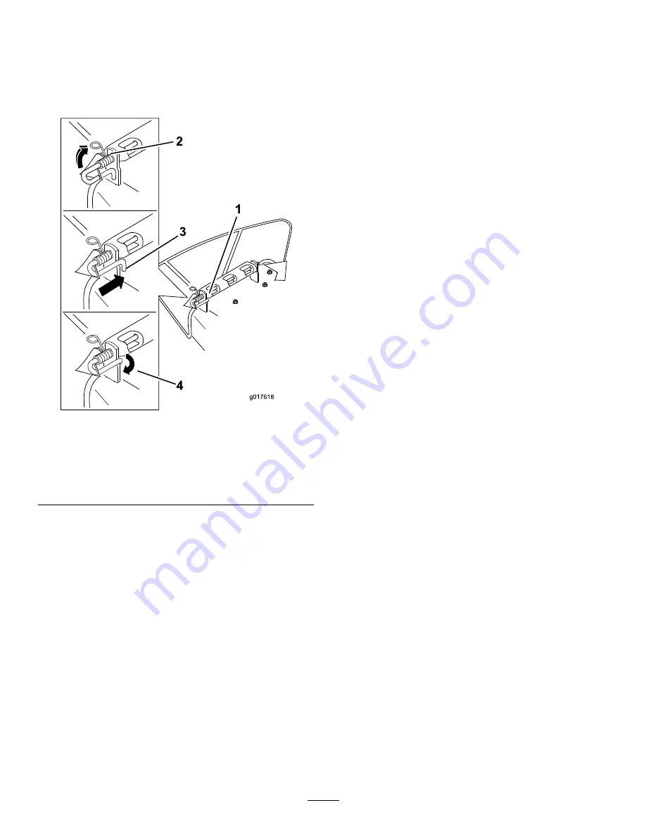
Position the spring on the rod as shown in so the
shorter spring end is coming from under the rod before
the bend and going over the rod as it returns from the
bend.
7.
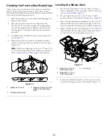
Lift the loop end of the spring and place it into the
notch on the deflector bracket (
).
g017618
1
3
4
2
g017618
Figure 76
1.
Rod and spring assembly
installed
3.
Rod (short end) moved
behind mower bracket
2.
Loop end of the spring
installed into the notch in
the deflector bracket
4.
Short end, retained by
mower bracket.
8.
Secure the rod and spring assembly by twisting it so the
short end of the rod is placed behind the front bracket
welded to the deck (
).
Important:
The grass deflector must be spring
loaded in the down position. Lift the deflector up
to test that it snaps to the full down position.
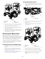
9.
Install the cotter pin (
Mower Belt Maintenance
Inspecting the Belts
Service Interval:
Every 25 hours—Check the belts for wear
or cracks.
Check the belts for cracks, frayed edges, burn marks, or any
other damage. Replace damaged belts.
Replacing the Mower Belt
Squealing when the belt is rotating, blades slipping when
cutting grass, frayed belt edges, burn marks, and cracks are
signs of a worn mower belt. Replace the mower belt if any of
these conditions are evident.
1.
Disengage the blade-control switch (PTO), move the
motion-control levers to the N
EUTRAL
-L
OCK
position,
and engage the parking brake.
2.
Shut off the engine, remove the key, and wait for all
moving parts to stop before leaving the operating
position.
3.
Lower the mower to the 76 mm (3 inches) height-of-cut
position.
4.
Remove the mower-deck curtain; refer to
Mower-Deck Curtain (page 33)
.
5.
For each of the belt covers, loosen the 2 bolts,
but do
not remove them.
6.
Slide the cover until it is clear of the bolts and lift it
up and out to remove it.
7.
Remove the floor pan to access the idler pulley.
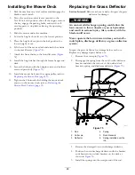
8.
Using a spring removal tool, (Toro Part No. 92-5771),
remove the idler spring from the deck post to remove
tension on the idler pulley (
49
Summary of Contents for TimeCutter HD X5450
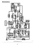
Page 55: ...Schematics g203461 Electrical Diagram Rev A 55 ...
Page 56: ...Notes ...
Page 57: ...Notes ...
Page 58: ...Notes ...


