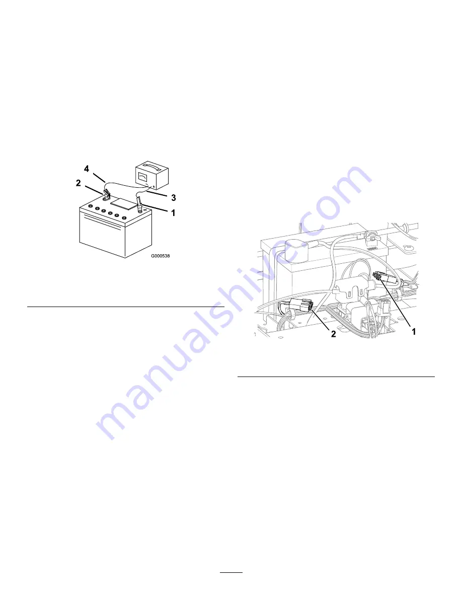
Charging the Battery
Service Interval:
Before storage—Charge the battery
and disconnect the battery cables.
1.
Remove the battery from the chassis; refer to
Removing the Battery (page 39)
.
2.
Charge the battery for a minimum of 1 hour at
6 to 10 A.
Note:
Do not overcharge the battery.
3.
When the battery is fully charged, unplug
the charger from the electrical outlet, then
disconnect the charger leads from the battery
posts (
g000538
Figure 50
1.
Positive (+) battery post
3.
Red (+) charger lead
2.
Negative (–) battery post
4.
Black (–) charger lead
Installing the Battery
1.
Position the battery in the tray (
).
2.
Using the fasteners previously removed, install
the positive (red) battery cable to the positive
(+) battery terminal.
3.
Using the fasteners previously removed, install
the negative battery cable to the negative (-)
battery terminal.
4.
Slide the red terminal boot onto the positive
(red) battery post.
5.
Secure the battery with the hold-down (
6.
Lower the seat.
Servicing the Fuses
The electrical system is protected by fuses. It requires
no maintenance; however, if a fuse blows, check the
component/circuit for a malfunction or short.
Fuse type:
•
Main—F1 (25 A, blade-type)
•
Charge Circuit—F2 (15 A, blade-type)
1.
Park the machine on a level surface, disengage
the blade-control switch, and move the
motion-control levers outward to the P
ARK
position.
2.
Shut off the engine, remove the key, and wait
for all moving parts to stop before leaving the
operating position.
3.
Raise the seat to access the fuses.
4.
To replace a fuse, pull out the fuse to remove
it (
g293931
Figure 51
1.
Charge circuit (15 A)
2.
Main (25 A)
5.
Lower the seat.
40
Summary of Contents for TimeCutter MX 4275T
Page 2: ......
Page 58: ...Schematics g307974 Electrical Diagram 139 2356 Rev A 56 ...
Page 59: ...Notes ...
Page 60: ...Notes ...
Page 62: ......
Page 71: ...decal140 2748 140 2748 decal142 5864 142 5864 9 ...
Page 121: ...Schaltbilder g307974 Elektrisches Schaltbild139 2356 Rev A 59 ...
Page 131: ...decal140 2748 140 2748 decal142 5864 142 5864 9 ...
Page 180: ...Schémas g307974 Schéma électrique139 2356 Rev A 58 ...
Page 181: ...Remarques ...
Page 238: ...Schema s g307974 Installatieschema139 2356 Rev A 56 ...
Page 240: ......


