background image

Storage

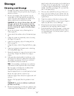
Cleaning and Storage

1.

Disengage the blade-control switch, move the motion
controls outward to the park position, stop the engine,
and remove the key.

2.

Remove grass clippings, dirt, and grime from the
external parts of the entire machine, especially the
engine. Clean dirt and chaff from the outside of the
engine cylinder head fins and blower housing.

Important:

You can wash the machine with mild

detergent and water. Do not pressure wash the
machine. Avoid excessive use of water, especially
near the control panel, engine, hydraulic pumps,
and motors.

3.

Service the air cleaner; refer to Servicing the Air
Cleaner (page 24).

4.

Grease and oil the machine; refer to Lubrication (page
24).

5.

Change the crankcase oil and filter; refer to Servicing
the Engine Oil (page 25).

6.

Check the tire pressure; refer to Checking the Tire
Pressure (page 31).

7.

Charge the battery; refer to Charging the Battery (page
29).

8.

Check the condition of the blades; refer to Servicing
the Cutting Blades (page 32).

9.

Prepare the machine for storage when non-use occurs
over 30 days. Prepare the machine for storage as
follows.

10.

Add a petroleum based stabilizer/conditioner to the
fuel in the tank. Follow the mixing instructions from
the stabilizer manufacturer. Do not use an alcohol
based stabilizer (ethanol or methanol).

Note:

A fuel stabilizer/conditioner is most effective

when mixed with fresh gasoline and used at all times.

Run the engine to distribute the conditioned fuel
through the fuel system (5 minutes).

Stop the engine, allow it to cool, and drain the fuel tank.

Restart the engine and run it until it stops.

Choke the engine. Start and run the engine until it will
not start.

Dispose of fuel properly. Recycle pursuant to local
codes.

Important:

Do not store stabilizer/conditioned

gasoline over 90 days.

11.

Remove the spark plug(s) and check its condition; refer
to Servicing the Spark Plug (page 27). With the spark

plug(s) removed from the engine, pour two tablespoons
of engine oil into the spark plug hole. Use the starter
to crank the engine and distribute the oil inside the
cylinder. Install the spark plug(s). Do not install the
wire on the spark plug(s).

12.

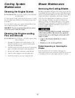
Clean any dirt and chaff from the top of the mower.

13.

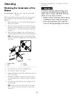
Scrape any heavy buildup of grass and dirt from the
underside of the mower, then wash the mower with
a garden hose.

14.

Check the condition of the drive and mower belts.

15.

Check and tighten all bolts, nuts, and screws. Repair or
replace any part that is worn or damaged.

16.

Paint all scratched or bare metal surfaces. Paint is
available from your Authorized Service Dealer.

17.

Store the machine in a clean, dry garage or storage area.
Remove the key from the ignition switch and keep it
in a memorable place. Cover the machine to protect
it and keep it clean.

41

Summary of Contents for TimeCutter SS 3216

Page 1: ...Form No 3381 516 Rev A TimeCutter SS 3216 Riding Mower Model No 74629 Serial No 314000001 and Up Register at www Toro com Original Instructions EN 3381 516 A ...

Page 2: ...ne manufacturer in accordance with the Society of Automotive Engineers SAE J1940 As configured to meet safety emission and operating requirements the actual engine torque on this class of mower will be significantly lower Go to www Toro com to view specifications on your mower model Introduction Read this information carefully to learn how to operate and maintain your product properly and to avoid...

Page 3: ...es 23 Raising the Seat 23 Lubrication 24 Greasing the Bearings 24 Engine Maintenance 24 Servicing the Air Cleaner 24 Servicing the Engine Oil 25 Servicing the Spark Plug 27 Fuel System Maintenance 28 Replacing the In line Fuel Filter 28 Electrical System Maintenance 29 Charging the Battery 29 Servicing the Fuses 30 Drive System Maintenance 31 Checking the Tire Pressure 31 Releasing the Electric Br...

Page 4: ...hine Clear the area of objects such as rocks toys wire etc which could be picked up and thrown by the blade Be sure the area is clear of other people before mowing Stop the machine if anyone enters the area Never carry passengers Do not mow in reverse unless absolutely necessary Always look down and behind before and while backing up Be aware of the mower discharge direction and do not point it at...

Page 5: ...rners shrubs trees the end of a fence or other objects that may obscure vision Towing Safety Do not attach towed equipment except at the hitch point Follow the attachment manufacturer s recommendation for weight limits for towed equipment and towing on slopes Towed weight must not exceed the weight of the machine operator and ballast Use counterweights or wheel weights as described in the attachme...

Page 6: ...riginal standards are maintained Toro Riding Mower Safety The following list contains safety information specific to Toro products or other safety information that you must know that may not be included in the ANSI standards Stop the engine move the motion control levers to neutral and outward to the park position disengage the blade control switch remove the key and disconnect the spark plug wire...

Page 7: ... degrees Use the slope chart to determine the degree of slope of hills before operating Do not operate this machine on a slope greater than 15 degrees Fold along the appropriate line to match the recommended slope 2 Align this edge with a vertical surface a tree building fence pole etc 3 Example of how to compare slope with folded edge 7 ...

Page 8: ...ance 2 Check tire pressure every 25 operating hours 3 Grease every 25 operating hours 4 Engine 110 6691 1 Thrown object hazard keep bystanders a safe distance from the machine 2 Thrown object hazard mower do not operate without the deflector discharge cover or grass collection system in place 3 Cutting dismemberment of hand or foot stay away from moving parts 114 1606 1 Entanglement hazard belt ke...

Page 9: ...tanders a safe distance from the battery 2 No fire open flame or smoking 7 Wear eye protection explosive gases can cause blindness and other injuries 3 Caustic liquid chemical burn hazard 8 Battery acid can cause blindness or severe burns 4 Wear eye protection 9 Flush eyes immediately with water and get medical help fast 5 Read the Operator s Manual 10 Contains lead do not discard 130 0780 1 Slow ...

Page 10: ...e slope slowly 3 Cutting dismemberment hazard mower blade entanglement hazard belt stay away from moving parts keep all guards and shields in place 7 Crushing dismemberment hazard of bystanders reversing crushing dismemberment hazard of bystanders do not carry passengers look behind and down when reversing 4 Thrown object hazard keep bystanders a safe distance from the machine pick up debris befor...

Page 11: ... lever The throttle controls the engine speed and it has a continuous variable setting from Slow to Fast Engage the choke by moving the lever past the Fast setting until it stops Figure 5 Blade control Switch Power Take Off The blade control switch represented by a power take off PTO symbol engages and disengages power to the mower blades Figure 5 Motion control Levers and Park Position The motion...

Page 12: ...olume such as E15 contains 15 ethanol E20 contains 20 ethanol or E85 contains up to 85 ethanol Using unapproved gasoline may cause performance problems and or engine damage which may not be covered under warranty Do not use gasoline containing methanol Do not store fuel either in the fuel tank or fuel containers over the winter unless a fuel stabilizer is used Do not add oil to gasoline DANGER In ...

Page 13: ...ioner in the machine to provide the following benefits Keeps gasoline fresh during storage of 90 days or less For longer storage it is recommended that the fuel tank be drained Cleans the engine while it runs Eliminates gum like varnish buildup in the fuel system which causes hard starting Important Do not use fuel additives containing methanol or ethanol Add the correct amount of gas stabilizer c...

Page 14: ...ury death or drowning A loss of traction is a loss of steering control To avoid loss of control and possibility of rollover Do not mow near drop offs or near water Do not mow slopes greater than 15 degrees Reduce the speed and use extreme caution on slopes When mowing slopes gradually work from lower to higher areas on the incline Avoid sudden turns or rapid speed changes Turn up into an incline w...

Page 15: ...d move the motion controls outward to the park position 2 Disengage the blades by moving the blade control switch to Off Figure 12 Figure 12 1 Control panel 2 Blade control switch Off position 3 Move the throttle lever to Choke before starting a cold engine Figure 13 Note It may be necessary to hold the lever against the stop in the choke position while trying to start the engine Note A warm or ho...

Page 16: ...te Always engage the blades with the throttle in the Fast position 3 Pull up on the blade control switch to move it to the On position and engage the blades Figure 15 Figure 15 1 Control panel 2 Blade control switch On position Disengaging the Blades Push down on the blade control switch to move it to the Off position and disengage the blades Figure 16 Figure 16 1 Control panel 2 Blade control swi...

Page 17: ...t idle speed for approximately one minute 4 Turn the ignition key to Off Figure 14 and remove the key Driving Driving the machine benefits from an understanding of what zero turn radius mower means The drive wheels turn independently powered by hydraulic motors on each axle hence one side can turn in reverse while the other turns forward causing the machine to spin rather than turn This vastly imp...

Page 18: ...ing harm to you or bystanders Always stop the machine and move the motion control levers to the park position before adjusting the Smart Speed Control System 2 Adjust the lever to the desired position Driving Forward 1 Move the levers to the center unlocked position 2 To go forward slowly push the motion control levers forward Figure 17 G008952 Figure 19 To go straight apply equal pressure to both...

Page 19: ...tempt to operate the mower while it is unattended Always remove the ignition key and move the motion control levers outward to the park position when leaving the machine unattended even if just for a few minutes Adjusting the Height of Cut Height of cut is controlled by the lever located to the right of the operating position Figure 21 G014476 1 2 3 Figure 21 1 Height of cut lever 3 115 mm 4 5 inc...

Page 20: ...stment for the opposite control lever Pushing the Machine by Hand Important Always push the machine by hand Do not tow the machine because damage may occur This machine has an electric brake mechanism and to push the machine the ignition key needs to be in the Run position The battery needs to be charged and functioning for the electric brake to be disengage Pushing the Machine 1 Park the machine ...

Page 21: ...top position to avoid draining the battery charge Note If the machine fails to move the electric brake may still be engaged If necessary the electric brake can be released manually refer to Releasing the Electric Brake page 31 Operating the Machine Move the bypass levers rearward through the key hole and down to lock them in place as shown in Figure 24 Note Ensure this is done for each lever 21 ...

Page 22: ...on Mowing at Correct Intervals Normally mow every 4 days But remember grass grows at different rates at different times So to maintain the same cutting height which is a good practice and mow more often in early spring As the grass growth rate slows in mid summer mow less frequently If you cannot mow for an extended period first mow at a high cutting height then mow again 2 days later at a lower h...

Page 23: ...engine oil filter Replace the spark plug Replace the in line fuel filter Clean the engine cooling fins and shrouds Before storage Charge the battery and disconnect battery cables Perform all maintenance procedures listed above before storage Paint any chipped surfaces Important Refer to your engine operator s manual for additional maintenance procedures CAUTION If you leave the key in the ignition...

Page 24: ... 25 operating hours 4 Engine 4 Connect a grease gun to each fitting Figure 25 and Figure 26 5 Pump grease into the fittings until grease begins to ooze out of the bearings Engine Maintenance Servicing the Air Cleaner Service Interval Before each use or daily Clean and check the air cleaner foam element Every 50 hours Replace the air cleaner paper element Note Service the air cleaner more frequentl...

Page 25: ...perate the engine with the complete foam and paper air cleaner assembly installed 1 Install the foam filter onto the paper filter Figure 28 2 Install the foam and paper filter onto the air cleaner housing 3 Install the air cleaner cover and tighten the 2 knobs Figure 27 Servicing the Engine Oil Oil Type Detergent oil API service SF SG SH SJ or higher Crankcase Capacity 1 0 L 34 oz when you do not ...

Page 26: ... oil drain valve 10 Remove the oil drain hose and wipe up any excess oil on the frame Note Dispose of the used oil at a certified recycling center 11 Change the engine oil filter refer to Changing the Engine oil Filter page 26 12 Slowly pour approximately 80 of the specified amount of oil into the fill hole Figure 31 13 Check the oil level refer to Checking the Engine oil Level page 25 14 Install ...

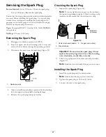
Page 27: ... 33 1 Spark plug wire 4 Clean around the spark plug to prevent dirt from falling into the engine and potentially causing damage 5 Remove the spark plug and metal washer Checking the Spark Plug 1 Inspect the spark plug Figure 34 Note If you see light brown or gray on the insulator the engine is operating properly A black coating on the insulator usually means that the air cleaner is dirty Figure 34...

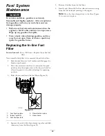
Page 28: ...ved from the fuel line 1 Park the machine on a level surface and disengage the blade control switch 2 Move the motion control levers outward to the park position stop the engine remove the key and wait for all moving parts to stop before leaving the operating position 3 Raise the seat and locate the fuel filters Figure 35 G017861 1 2 3 4 5 Figure 35 1 Fuel line to engine 4 Flow direction arrow 2 I...

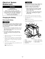
Page 29: ...k position stop the engine remove the key and wait for all moving parts to stop before leaving the operating position 3 Raise the seat to access the battery 4 Disconnect the negative black ground cable from the battery post Figure 36 Note Retain all fasteners WARNING Incorrect battery cable routing could damage the machine and cables causing sparks Sparks can cause the battery gasses to explode re...

Page 30: ...o the positive battery terminal 3 Using the fasteners previously removed install the negative battery cable to the negative battery terminal 4 Slide the red terminal boot onto the positive red battery post 5 Secure the battery with the hold down Figure 36 6 Lower the seat Servicing the Fuses The electrical system is protected by fuses It requires no maintenance however if a fuse blows check the co...

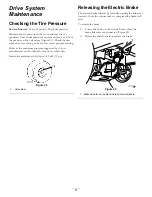
Page 31: ...m pressure suggested by the tire manufacturer on the sidewall of the caster wheel tires Inflate the rear drive wheel tires to 82 kPa 12 psi Figure 39 1 Valve stem Releasing the Electric Brake The electric brake releases by manually rotating the link arms forward Once the electric brake is energized the brake will reset To release the brake 1 Locate the shaft on the electric brake where the brake l...

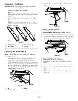
Page 32: ...ine parts 5 Install the air intake screen and cooling shrouds Mower Maintenance Servicing the Cutting Blades Maintain sharp blades throughout the cutting season because sharp blades cut cleanly without tearing or shredding the grass blades Tearing and shredding turns grass brown at the edges which slows growth and increases the chance of disease Check the cutter blades daily for sharpness and for ...

Page 33: ...While wearing thickly padded gloves or other adequate hand protection slowly rotate the blade to be measure into a position that allows effective measurement of the distance between the cutting edge and the level surface the machine is on Figure 42 G009679 1 2 3 Figure 42 1 Deck 3 Blade 2 Spindle housing 3 Measure from the tip of the blade to the flat surface Figure 43 G009680 1 2 3 Figure 43 1 Bl...

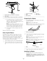
Page 34: ...n non conformance with safety standards 1 Hold the blade end using a rag or thickly padded glove 2 Remove the blade bolt the curved washer the blade stiffener and the blade from the spindle shaft Figure 46 Figure 46 1 Sail area of the blade 4 Blade bolt 2 Blade 5 Blade stiffener 3 Curved washer Sharpening the Blades 1 Use a file to sharpen the cutting edge at both ends of the blade Figure 47 Note ...

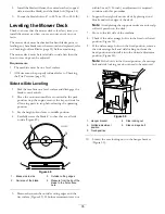
Page 35: ...e position 4 Carefully rotate the blade s so that they are all side to side Figure 49 G014630 1 2 3 4 4 Figure 49 1 Blade side to side 3 Outside cutting edges 2 Sail area of the blade 4 Measure from the tip of the blade to the flat surface here 5 Measure between the outside cutting edges and the flat surface Figure 49 If both measurements are not within 5 mm 3 16 inch an adjustment is required con...

Page 36: ...n 7 9 mm 5 16 inch lower than the rear of the mower adjust the blade level using the following instructions 1 Park the machine on a level surface and disengage the blade control switch 2 Move the motion control levers outward to the park position stop the engine remove the key and wait for all moving parts to stop before leaving the operating position 3 Set the height of cut lever to middle positi...

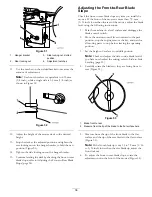
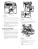
Page 37: ...ntrol levers outward to the park position stop the engine remove the key and wait for all moving parts to stop before leaving the operating position 3 Lower the height of cut lever to the lowest position 4 Remove the hairpin cotter from the front support rod and remove the rod from the deck bracket Figure 55 Carefully lower the front of the mower deck to the ground G014635 1 2 3 Figure 55 1 Front ...

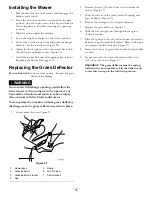
Page 38: ... result in serious injury Also contact with the blade could occur Never operate the machine without grass deflector discharge cover or grass collection system in place 1 Locate items shown in Figure 57 G014636 1 2 3 4 5 6 7 Figure 57 1 Mower deck 5 Spring 2 Grass deflector 6 Nut 3 8 inch 3 Grass deflector bracket 7 Short standoff 4 Rod 2 Remove the nut 3 8 inch from the rod under the mower Figure ...

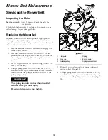
Page 39: ... the key and wait for all moving parts to stop before leaving the operating position 3 Set the height of cut at the lowest cutting position 38 mm 1 1 2 inches 4 Using a spring removal tool Toro part no 92 5771 remove the idler spring from the deck hook to remove tension on the idler pulley and roll the belt off of the pulleys Figure 58 WARNING The spring is under tension when installed and can cau...

Page 40: ... 3 4 Figure 59 1 Washout fitting 3 O ring 2 Hose 4 Coupling 4 Lower the mower to the lowest height of cut 5 Sit on the seat and start the engine 6 Engage the blade control switch and let the mower run for 1 to 3 minutes 7 Disengage the blade control switch stop the engine remove the ignition key and wait for all moving parts to stop 8 Turn the water off and remove the coupling from the washout fit...

Page 41: ...hanol or methanol Note A fuel stabilizer conditioner is most effective when mixed with fresh gasoline and used at all times Run the engine to distribute the conditioned fuel through the fuel system 5 minutes Stop the engine allow it to cool and drain the fuel tank Restart the engine and run it until it stops Choke the engine Start and run the engine until it will not start Dispose of fuel properly...

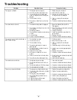
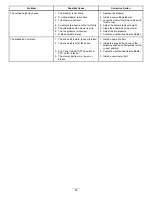
Page 42: ...e spark plug wire s is loose or disconnected 4 Install the wire s on the spark plug 5 The spark plug s is pitted fouled or the gap is incorrect 5 Install a new correctly gapped spark plug s 6 There is dirt in fuel filter 6 Replace the fuel filter 7 Dirt water or stale fuel is in fuel system 7 Contact an Authorized Service Dealer 8 There is incorrect fuel in the fuel tank 8 Drain the tank and repla...

Page 43: ...erside of the mower 6 The tire pressure is incorrect 6 Adjust the tire pressure The cutting height is uneven 7 A blade spindle is bent 7 Contact an Authorized Service Dealer 1 The drive belt is worn loose or broken 1 Install a new drive belt 2 The drive belt is off of the pulley 2 Install the drive belt and check the adjusting shafts and belt guides for the correct position 3 The Power Take Off PT...

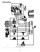
Page 44: ...Schematics G014644 Electrical Diagram Rev A 44 ...

Page 45: ...Notes 45 ...

Page 46: ...Notes 46 ...

Page 47: ...Notes 47 ...

Page 48: ...u are dissatisfied with the Service Dealer s analysis or with the assistance provided contact us at Customer Care Department RLC Division Toro Warranty Company 8111 Lyndale Avenue South Bloomington MN 55420 1196 Toll free at 866 216 6029 U S customers Toll free at 866 216 6030 Canadian customers Items and Conditions Not Covered There is no other express warranty except for special emission system ...

Reviews: