background image

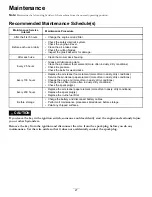
Servicing the Engine Oil

Oil Type:

Detergent oil (API service SF, SG, SH, SJ, or SL)

Crankcase Capacity:

2.0 L (67.6 oz)

Viscosity:

See the table below.

SAE 5W

-30, 10W -30

SAE 30

SYNTHETIC 5W -20, 5W -30, 10W -30

g029683

Figure 30

Checking the Engine-Oil Level

Service Interval:

Before each use or daily

Note:

Check the oil when the engine is cold.

WARNING

Contact with hot surfaces may cause personal
injury.

Keep hands, feet, face, clothing, and other body
parts away the muffler and other hot surfaces.

Important:

Do not overfill the crankcase with oil,

because damage to the engine may result. Do not run
engine with oil below the Low mark, because the engine
may be damaged.

1.

Park the machine on a level surface, disengage the
blade-control switch, stop the engine, engage parking
brake, and remove the key.

2.

Make sure the engine is stopped, level, and is cool, so
the oil has had time to drain into the sump.

3.

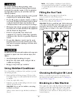
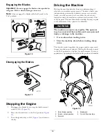
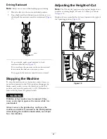
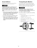
To keep dirt, grass clippings, etc., out of the engine,
clean the area around the oil-fill cap and dipstick before
removing it (

Figure 31

).

B

A

C

D

E

G029368

F

G

H

I

J           K

Figure 31

Changing the Engine Oil and Oil Filter

Service Interval:

After the first 5 hours/After the first

month (whichever comes first)—Change
the engine oil and filter.

Every 100 hours/Yearly (whichever comes
first)—Change the engine oil (more often in dusty,
dirty conditions).

Every 100 hours/Yearly (whichever comes
first)—Change the oil filter (more often in dusty, dirty
conditions).

Note:

Change the engine-oil filter more frequently when

operating conditions are extremely dusty or sandy.

Note:

Dispose of the used oil at a recycling center.

1.

Park the machine on a level surface to ensure the oil
drains completely.

2.

Disengage the PTO and ensure the parking brake is
engaged.

3.

Stop the engine, remove the key, and wait for all moving
parts to stop before leaving the operating position.

30


Summary of Contents for TimeCutter SS 5000

Page 1: ...Form No 3393 111 Rev B TimeCutter SS 5000 Riding Mower Model No 74731 Serial No 315000001 and Up Register at www Toro com Original Instructions EN 3393 111 B ...

Page 2: ...del Introduction This machine is a ride on rotary blade lawnmower intended to be used by homeowners in residential applications It is primarily designed for cutting grass on well maintained lawns It is not designed for cutting brush mowing grass and other growth alongside highways or for agricultural uses Read this information carefully to learn how to operate and maintain your product properly an...

Page 3: ...tion Control Levers 23 Pushing the Machine by Hand 23 Grass Deflector 24 Transporting the Machine 24 Loading the Machine 25 Operating Tips 26 Maintenance 27 Recommended Maintenance Schedule s 27 Premaintenance Procedures 28 Raising the Seat 28 Lubrication 28 Greasing the Bearings 28 Engine Maintenance 29 Servicing the Air Cleaner 29 Servicing the Engine Oil 30 Servicing the Spark Plug 32 Cleaning ...

Page 4: ...behind and to the side before changing directions Never leave a running machine unattended Always turn off blades set parking brake stop engine and remove key before dismounting Turn off blades when not mowing Stop the engine wait for all parts to come to a complete stop and remove the key before cleaning the machine removing the grass catcher or unclogging the discharge chute Operate the machine ...

Page 5: ...t of the towed load Travel slowly and allow extra distance to stop Make wide turns to keep the attachment clear of the machine Service Safe Handling of Gasoline To avoid personal injury or property damage use extra care when handling gasoline and other fuels They are flammable and the vapors are explosive Extinguish all cigarettes cigars pipes and other sources of ignition Use only an approved fue...

Page 6: ...er and any moving parts while engine is running Do not touch equipment or attachment parts which may be hot from operation Allow to cool before attempting to maintain adjust or service Battery acid is poisonous and can cause burns Avoid contact with skin eyes and clothing Protect your face eyes and clothing when working with a battery Battery gases can explode Keep cigarettes sparks and flames awa...

Page 7: ... degrees Use the slope chart to determine the degree of slope of hills before operating Do not operate this machine on a slope greater than 15 degrees Fold along the appropriate line to match the recommended slope 2 Align this edge with a vertical surface a tree building fence pole etc 3 Example of how to compare slope with folded edge 7 ...

Page 8: ...tructions before servicing or performing maintenance 2 Check tire pressure every 25 operating hours 3 Grease every 25 operating hours 4 Engine 110 6691 1 Thrown object hazard keep bystanders a safe distance from the machine 2 Thrown object hazard mower do not operate without the deflector discharge cover or grass collection system in place 3 Cutting dismemberment of hand or foot stay away from mov...

Page 9: ...ear eye protection explosive gases can cause blindness and other injuries 3 Caustic liquid chemical burn hazard 8 Battery acid can cause blindness or severe burns 4 Wear eye protection 9 Flush eyes immediately with water and get medical help fast 5 Read the Operator s Manual 10 Contains lead do not discard 121 2989 1 Bypass lever position for pushing the machine 2 Bypass lever position for operati...

Page 10: ...131 1097 1 Oil drain 131 4036 1 Maximum drawbar pull 36 kg 80 lb 2 Read the Operator s Manual 132 6863 131 3947 1 Trim slow 3 Mow fast 2 Tow medium 10 ...

Page 11: ...121 0773 1 Fast 4 Choke 2 Continuous variable setting 5 Power take off PTO Blade control switch 3 Slow 11 ...

Page 12: ...and that has an incline less than 15 degrees back up the ramp in reverse and drive forward off the ramp 7 Tipping hazard on slopes do not use on slopes near open water do not use on slopes greater than 15 degrees 2 Warning before servicing engage the parking brake remove the key and the spark plug connection 4 Thrown object hazard keep bystanders away from the machine remove debris from the area b...

Page 13: ...4 1 Footrest 8 Gas tank cap 2 Deflector 9 Smart Speed lever 3 Height of cut lever 10 Rear drive wheel 4 Motion control lever 11 Mower deck 5 Control panel 12 Anti scalp roller 6 Operator seat 13 Front caster wheel 7 Engine 13 ...

Page 14: ...wn on the choke control for normal engine operation Blade Control Switch Power Take off The blade control switch represented by a power take off PTO symbol engages and disengages power to the mower blades Figure 5 Motion Control Levers and Park Position The motion control levers are speed sensitive controls of independent wheel motors Moving a lever forward or backward turns the wheel on the same ...

Page 15: ...hanol by volume such as E15 contains 15 ethanol E20 contains 20 ethanol or E85 contains up to 85 ethanol Using unapproved gasoline may cause performance problems and or engine damage which may not be covered under warranty Do not use gasoline containing methanol Do not store fuel either in the fuel tank or fuel containers over the winter unless a fuel stabilizer is used Do not add oil to gasoline ...

Page 16: ...e following benefits Keeps gasoline fresh during storage of 90 days or less For longer storage it is recommended that the fuel tank be drained Cleans the engine while it runs Eliminates gum like varnish buildup in the fuel system which causes hard starting Important Do not use fuel additives containing methanol or ethanol Add the correct amount of gas stabilizer conditioner to the gas Note A fuel ...

Page 17: ...s ear and can cause hearing loss through extended periods of exposure Wear hearing protection when operating this machine G009027 1 2 Figure 10 1 Wear safety glasses 2 Wear hearing protection Understanding the Safety Interlock System WARNING If safety interlock switches are disconnected or damaged the machine could operate unexpectedly causing personal injury Do not tamper with the interlock switc...

Page 18: ... control levers to the center unlocked position engage the blade control switch and rise slightly from the seat Note The engine should stop Starting the Engine Note A warm or hot engine may not require choking Important Do not engage the starter for more than 5 seconds at a time Engaging the starter motor for more than 5 seconds can damage the starter motor If the engine fails to start wait 10 sec...

Page 19: ...y hydraulic motors on each axle hence one side can turn in reverse while the other turns forward causing the machine to spin rather than turn This vastly improves the machine maneuverability but may require some adjustment if the operator is unfamiliar WARNING The machine can spin very rapidly The operator may lose control of the machine and cause personal injury or damage to the machine Use cauti...

Page 20: ...wing X Transport X Trim This is the lowest speed The suggested uses for this speed are as follows Parking Heavy wet grass mowing conditions Training Tow This is the medium speed The suggested uses for this speed are as follows Bagging Mulching Mow This is the fastest speed The suggested uses for this speed are as follows Normal mowing Transporting the machine Driving Forward 1 Move the levers to t...

Page 21: ...eutral and outward to the PARK position disengage the blade control switch ensure the throttle is in the FAST position and turn the ignition key to OFF Remember to remove the key from the ignition switch WARNING Children or bystanders may be injured if they move or attempt to operate the mower while it is unattended Always remove the ignition key and move the motion control levers outward to the P...

Page 22: ... the blade control switch PTO move the motion control levers to the NEUTRAL LOCK position and set the parking brake 2 Stop the engine remove the key and wait for all moving parts to stop before leaving the operating position 3 Adjust the anti scalp rollers as shown in Figure 19 to match the closest height of cut position G010233 1 2 3 4 Figure 19 1 Anti scalp roller 3 Flange nut 2 Bolt 4 Hole spac...

Page 23: ...he blade control switch 2 Move the motion control levers outward to PARK position stop the engine and wait for all moving parts to stop before leaving the operating position 3 Locate the bypass levers on the frame on both sides of the engine 4 Move the bypass levers forward through the key hole and down to lock them in place as shown in Figure 22 Ensure this is done for each lever 5 Move the motio...

Page 24: ... the wire off the spark plug s Transporting the Machine Use a heavy duty trailer or truck to transport the machine Ensure that the trailer or truck has all necessary brakes lighting and marking as required by law Please carefully read all the safety instructions Knowing this information could help you your family pets or bystanders avoid injury WARNING Driving on the street or roadway without turn...

Page 25: ...slope This will minimize the ramp angle WARNING Loading a machine onto a trailer or truck increases the possibility of tip over and could cause serious injury or death Use extreme caution when operating a machine on a ramp Use only a full width ramp do not use individual ramps for each side of the machine Do not exceed a 15 degree angle between the ramp and the ground or between the ramp and the t...

Page 26: ...tion Mow at Correct Intervals Normally mow every four days But remember grass grows at different rates at different times So to maintain the same cutting height which is a good practice mow more often in early spring As the grass growth rate slows in mid summer mow less frequently If you cannot mow for an extended period first mow at a high cutting height then mow again two days later at a lower h...

Page 27: ...ement more often in dusty dirty conditions Service the air cleaner paper element more often in dusty dirty conditions Change the engine oil more often in dusty dirty conditions Change the oil filter more often in dusty dirty conditions Check the spark plug s Every 200 hours Replace the air cleaner paper element more often in dusty dirty conditions Replace the spark plug s Replace the in line fuel ...

Page 28: ... 2 Move the motion control levers outward to the PARK position stop the engine remove the key and wait for all moving parts to stop before leaving the operating position 3 Clean the grease fittings Figure 26 and Figure 27 with a rag Make sure to scrape any paint off of the front of the fitting s 1 G014522 Figure 26 1 Front caster tire Figure 27 Located on the seat pan underside 1 Read the instruct...

Page 29: ... Every 25 hours Monthly whichever comes first Clean the air cleaner foam element more often in dusty dirty conditions Every 100 hours Yearly whichever comes first Replace the air cleaner foam element more often in dusty dirty conditions Wash the foam element with water and replace the foam element if it is damaged Servicing the Paper Element Service Interval Every 100 hours Yearly whichever comes ...

Page 30: ...ed level and is cool so the oil has had time to drain into the sump 3 To keep dirt grass clippings etc out of the engine clean the area around the oil fill cap and dipstick before removing it Figure 31 B A C D E G029368 F G H I J K Figure 31 Changing the Engine Oil and Oil Filter Service Interval After the first 5 hours After the first month whichever comes first Change the engine oil and filter E...

Page 31: ...ure 32 g027799 A B C D E F G H g029570 Figure 32 5 Change the engine oil filter Figure 33 B A C D E F 3 4 g027477 Figure 33 Note Ensure that the oil filter gasket touches the engine and then turn the filter an extra 3 4 turn 31 ...

Page 32: ...9YC or NGK BPR6ES Air gap 0 76 mm 0 03 inch Removing the Spark Plug 1 Disengage the PTO and ensure the parking brake is engaged 2 Stop the engine remove the key and wait for all moving parts to stop before leaving the operating position B A g027478 Figure 35 Note Due to the deep recess around the spark plug blowing out the cavity with compressed air is usually the most effective method for cleanin...

Page 33: ... the air filter Fuel System Maintenance DANGER In certain conditions gasoline is extremely flammable and highly explosive A fire or explosion from gasoline can burn you and others and can damage property Perform any fuel related maintenance when the engine is cold Do this outdoors in an open area Wipe up any gasoline that spills Never smoke when draining gasoline and stay away from an open flame o...

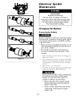
Page 34: ...o not allow metal tools to short between the battery terminals and metal parts of the machine 1 Park the machine on a level surface and disengage the blade control switch 2 Move the motion control levers outward to the PARK position stop the engine remove the key and wait for all moving parts to stop before leaving the operating position 3 Raise the seat to access the battery 4 Disconnect the nega...

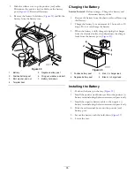
Page 35: ...ry 2 Charge the battery for a minimum of 1 hour at 6 to 10 amps Do not overcharge the battery 3 When the battery is fully charged unplug the charger from the electrical outlet then disconnect the charger leads from the battery posts Figure 40 Figure 40 1 Positive battery post 3 Red charger lead 2 Negative battery post 4 Black charger lead Installing the Battery 1 Position the battery in the tray F...

Page 36: ...2 1 Figure 41 1 Main 30 amp 2 Charge circuit 25 amp 4 Return the control panel to its original position Use the screws removed previously to secure the panel to the machine Drive System Maintenance Checking the Tire Pressure Service Interval Every 25 hours Check tire pressure Maintain the air pressure in the front and rear tires as specified Uneven tire pressure can cause uneven cut Check the pres...

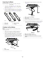
Page 37: ...hredding turns grass brown at the edges which slows growth and increases the chance of disease Check the cutter blades daily for sharpness and for any wear or damage File down any nicks and sharpen the blades as necessary If a blade is damaged or worn replace it immediately with a genuine Toro replacement blade For convenient sharpening and replacement you may want to keep extra blades on hand WAR...

Page 38: ...sition also considered the transport position 2 While wearing thickly padded gloves or other adequate hand protection slowly rotate blade to be measured into a position that allows effective measurement of the distance between the cutting edge and the level surface the machine is on Figure 45 G014972 1 2 3 Figure 45 1 Deck 3 Blade 2 Spindle housing 3 Measure from the tip of the blade to the flat s...

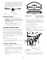
Page 39: ...indle could be bent Contact an Authorized Toro Dealer for service B If the variance is within constraints move to the next blade Repeat this procedure on each blade Removing the Blades The blades must be replaced if a solid object is hit if the blade is out of balance or the blade is bent To ensure optimum performance and continued safety conformance of the machine use genuine Toro replacement bla...

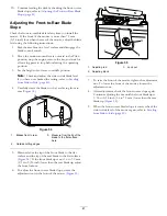
Page 40: ... must be on a level surface All four tire must be properly inflated Refer to Checking the Tire Pressure page 36 Leveling from Side to Side 1 Park the machine on a level surface and disengage the blade control switch 2 Move the motion control levers outward to the PARK position stop the engine remove the key and wait for all moving parts to stop before leaving the operating position 3 Set the heigh...

Page 41: ...s so they are facing front to rear Figure 54 G009659 1 2 3 2 3 Figure 54 1 Blades front to rear 3 Measure from the tip of the blade to the flat surface here 2 Outside cutting edges 5 Measure from the tip of the front blade to the flat surface and the tip of the rear blade to the flat surface Figure 54 If the front blade tip is not 1 6 to 7 9 mm 1 16 to 5 16 inch lower than the rear blade tip adjus...

Page 42: ... rod and remove the rod from the deck bracket Figure 48 Carefully lower the front of the mower deck to the ground G014635 1 2 3 Figure 56 1 Front support rod 3 Deck bracket 2 Locking nut 5 Lift the mower deck and hanger brackets clear of the rear lift rod and lower the mower carefully to the ground Figure 57 2 2 3 G005077 1 2 2 3 Figure 57 1 Mower deck 3 Rear lift rod 2 Hanger bracket 6 Slide the ...

Page 43: ...re 58 WARNING The spring is under tension when installed and can cause personal injury Be careful when removing the belt G014931 1 2 3 3 4 5 6 Figure 58 1 Idler pulley 4 Spring 2 Mower belt 5 Engine pulley 3 Outside pulley 6 Spring removal too 5 Route the new belt around the engine pulley and mower pulleys Figure 58 6 Using a spring removal tool Toro part no 92 5771 install the idler spring over t...

Page 44: ...flector 6 Nut 3 8 inch 3 Grass deflector bracket 7 Short stand off 4 Rod 2 Remove the nut 3 8 inch from the rod under the mower Figure 59 3 Slide the rod out of the short stand off spring and grass deflector Figure 59 Remove the damaged or worn grass deflector 4 Replace the grass deflector Figure 59 5 Slide rod straight end through the rear grass deflector bracket 6 Place the spring on the rod wit...

Page 45: ...troleum jelly on the washout fitting O ring to make the coupling slide on easier and protect the O ring Figure 60 1 Washout fitting 3 O ring 2 Hose 4 Coupling 4 Lower the mower to the lowest height of cut 5 Sit on the seat and start the engine Engage the blade control switch and let the mower run for 1 to 3 minutes 6 Disengage the blade control switch stop the engine and remove the ignition key Wa...

Page 46: ...the tank Follow the mixing instructions from the stabilizer manufacturer Do not use an alcohol based stabilizer ethanol or methanol Note A fuel stabilizer conditioner is most effective when mixed with fresh gasoline and used at all times Run the engine to distribute the conditioned fuel through the fuel system 5 minutes Important Do not store stabilizer conditioned gasoline over 90 days 11 Remove ...

Page 47: ...he choke lever to ON 3 The air cleaner is dirty 3 Clean or replace the air cleaner element 4 The spark plug wire s is loose or disconnected 4 Install the wire s on the spark plug 5 The spark plug s is pitted fouled or the gap is incorrect 5 Install a new correctly gapped spark plug s 6 There is dirt in fuel filter 6 Replace the fuel filter 7 Dirt water or stale fuel is in fuel system 7 Contact an ...

Page 48: ...ation 6 A blade spindle is bent 6 Contact an Authorized Service Dealer 1 The blade s is not sharp 1 Sharpen the blade s 2 A cutting blade s is are bent 2 Install a new cutting blade s 3 The mower is not level 3 Level the mower from side to side and front to rear 4 An anti scalp wheel is not set correctly 4 Adjust the anti scalp wheel height 5 The underside of the mower is dirty 5 Clean the undersi...

Page 49: ...Schematics Electrical Diagram Rev A 49 ...

Page 50: ...Notes 50 ...

Page 51: ...Notes 51 ...

Page 52: ...u are dissatisfied with the Service Dealer s analysis or with the assistance provided contact us at Customer Care Department RLC Division Toro Warranty Company 8111 Lyndale Avenue South Bloomington MN 55420 1196 Toll free at 866 216 6029 U S customers Toll free at 866 216 6030 Canadian customers Items and Conditions Not Covered There is no other express warranty except for special emission system ...

Reviews: