background image

RELEASED Ver-C ©Toro 2016

Form No. 3393-925 Rev C

TimeCutter

®

SW Riding Mower

Model No. SW TimeCutter Models

Setup Instructions

Setup

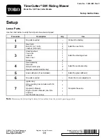
Loose Parts

Use the chart below to verify that all parts have been shipped.

Procedure

Description

Qty.

Use

1

No parts required

Connect the battery.

Rear hitch

1

Bolt (5/16 x 1 inch)

2

2

Locknut (5/16 inch)

2

Install the rear hitch.

Steering wheel

1

Top cover

1

Locknut

1

Rear cover

1

3

Screws

2

Install the steering wheel.

Seat assembly

1

Seat rod

1

Hairpin cotter pins

2

4

Spacers (certain models only)

2

Install the seat assembly.

5

Grass deflector (if not installed)

1

Install the grass deflector.

6

No parts required

Check the mower adjustment.

Ignition key

1

Hose coupling (not included with CE
models)

1

Operator's Manual

1

Engine Owner’s Manual (non-Toro
engines)

1

7

KeyChoice® key (blue)

1

Complete the setup.

Note:

Determine the left and right sides of the machine from the normal operating position.

© 2016—The Toro® Company
8111 Lyndale Avenue South
Bloomington, MN 55420

Register at www.Toro.com.

Original Instructions (EN)

Printed in the USA

All Rights Reserved

*3393-925* C


Summary of Contents for TimeCutter SW Series

Page 1: ...el Seat assembly 1 Seat rod 1 Hairpin cotter pins 2 4 Spacers certain models only 2 Install the seat assembly 5 Grass deflector if not installed 1 Install the grass deflector 6 No parts required Check the mower adjustment Ignition key 1 Hose coupling not included with CE models 1 Operator s Manual 1 Engine Owner s Manual non Toro engines 1 7 KeyChoice key blue 1 Complete the setup Note Determine t...

Page 2: ...egative battery post 3 Remove the fasteners on the negative battery cable and use them to secure the negative battery cable to the negative battery post Figure 1 G018395 2 1 4 3 6 5 g018395 Figure 1 1 Negative battery cable 4 Negative battery post cap 2 Wing nut 5 Carriage bolt 3 Washer 6 Negative battery post 2 Installing the Rear Hitch Parts needed for this procedure 1 Rear hitch 2 Bolt 5 16 x 1...

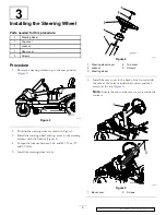
Page 3: ...steering wheel and top cover to the steering column with the locknut Figure 4 4 Torque the locknut between 36 6 and 44 7 N m 27 and 33 ft lb 5 Install the steering wheel cover g027737 Figure 4 1 Steering wheel cover 4 Top cover 2 Locknut 5 Column 3 Steering wheel 6 Install the rear cover to the back of the footrest with the tabs at the bottom inside the footrest and the 2 screws in the top Figure ...

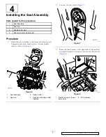
Page 4: ...irpin cotter pins and 2 spacers certain models only as shown in Figure 6 g027723 Figure 6 1 Seat assembly 3 Hairpin cotter 2 Spacers 4 Seat rod with hairpin cotter installed 2 Connect the seat switch Figure 7 g027695 g027695 Figure 7 3 Route the wire harness to the right side of the machine and push the plastic connector into the seat frame hole Figure 8 g028383 1 2 g028383 Figure 8 1 Plastic conn...

Page 5: ...up Parts needed for this procedure 1 Ignition key 1 Hose coupling not included with CE models 1 Operator s Manual 1 Engine Owner s Manual non Toro engines 1 KeyChoice key blue Procedure Checking the Tire Pressure Check the front and rear tires for proper inflation refer to Checking the Tire Pressure in the Operator s Manual for the recommended inflation pressure Checking the Side Discharge Chute R...

Page 6: ...RELEASED Ver C Toro 2016 Notes ...

Page 7: ...RELEASED Ver C Toro 2016 Notes ...

Page 8: ...RELEASED Ver C Toro 2016 ...

Reviews: