background image

RELEASED Ver-C ©Toro 2016

3

Installing the Steering Wheel

Parts needed for this procedure:

1

Steering wheel

1

Top cover

1

Locknut

1

Rear cover

2

Screws

Procedure

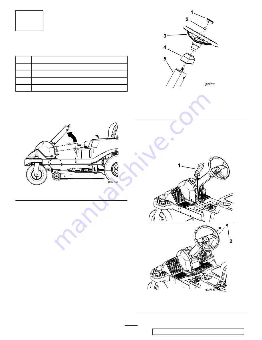
1.

Rotate the steering column up to the user position
(

Figure 3

).

g027703

Figure 3

2.

Position the steering wheel as shown in

Figure 5

.

3.

Install the steering wheel and top cover to the steering
column with the locknut (

Figure 4

).

4.

Torque the locknut between 36.6 and 44.7 N-m (27
and 33 ft-lb).

5.

Install the steering-wheel cover.

g027737

Figure 4

1.

Steering-wheel cover

4.

Top cover

2.

Locknut

5.

Column

3.

Steering wheel

6.

Install the rear cover to the back of the footrest with
the tabs at the bottom inside the footrest and the 2
screws in the top (

Figure 5

).

Note:

Ensure the tabs of the rear cover are inside the

footrest.

g027887

Figure 5

1.

Back cover

2.

Screws

3


Summary of Contents for TimeCutter SW Series

Page 1: ...el Seat assembly 1 Seat rod 1 Hairpin cotter pins 2 4 Spacers certain models only 2 Install the seat assembly 5 Grass deflector if not installed 1 Install the grass deflector 6 No parts required Check the mower adjustment Ignition key 1 Hose coupling not included with CE models 1 Operator s Manual 1 Engine Owner s Manual non Toro engines 1 7 KeyChoice key blue 1 Complete the setup Note Determine t...

Page 2: ...egative battery post 3 Remove the fasteners on the negative battery cable and use them to secure the negative battery cable to the negative battery post Figure 1 G018395 2 1 4 3 6 5 g018395 Figure 1 1 Negative battery cable 4 Negative battery post cap 2 Wing nut 5 Carriage bolt 3 Washer 6 Negative battery post 2 Installing the Rear Hitch Parts needed for this procedure 1 Rear hitch 2 Bolt 5 16 x 1...

Page 3: ...steering wheel and top cover to the steering column with the locknut Figure 4 4 Torque the locknut between 36 6 and 44 7 N m 27 and 33 ft lb 5 Install the steering wheel cover g027737 Figure 4 1 Steering wheel cover 4 Top cover 2 Locknut 5 Column 3 Steering wheel 6 Install the rear cover to the back of the footrest with the tabs at the bottom inside the footrest and the 2 screws in the top Figure ...

Page 4: ...irpin cotter pins and 2 spacers certain models only as shown in Figure 6 g027723 Figure 6 1 Seat assembly 3 Hairpin cotter 2 Spacers 4 Seat rod with hairpin cotter installed 2 Connect the seat switch Figure 7 g027695 g027695 Figure 7 3 Route the wire harness to the right side of the machine and push the plastic connector into the seat frame hole Figure 8 g028383 1 2 g028383 Figure 8 1 Plastic conn...

Page 5: ...up Parts needed for this procedure 1 Ignition key 1 Hose coupling not included with CE models 1 Operator s Manual 1 Engine Owner s Manual non Toro engines 1 KeyChoice key blue Procedure Checking the Tire Pressure Check the front and rear tires for proper inflation refer to Checking the Tire Pressure in the Operator s Manual for the recommended inflation pressure Checking the Side Discharge Chute R...

Page 6: ...RELEASED Ver C Toro 2016 Notes ...

Page 7: ...RELEASED Ver C Toro 2016 Notes ...

Page 8: ...RELEASED Ver C Toro 2016 ...

Reviews: