background image

5

2.

Install 

t

he front weight to the bottom footrest frame

with 2 bolts (3/8 x 2–1/4 inch), 4 washers (3/8 inch) and

2 nuts (3/8 inch) (Figure 3).

Note:

 Make sure the weight is installed as shown in

Figure 3.

3.

Install the footrest into the footrest frame while placing

the rods in the same hole positions (Fig. 2).

2

4

m–6686

5

4

3

1

Figure 3

1. Footrest frame
2. Bolt,  3/8 x 2–1/4 inch
3. Front weight

4. Washer, 3/8 inch
5. Nut, 3/8 inch

Important


When you remove the twin bagger,

remember to remove the front weight.

Installing the Quick Attach

Bracket

1.

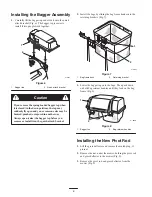
From the back of the mower, slide the quick attach

bracket along the outside of the rear frame.

2.

Align the holes in the rear frame and the bagger

mounting bracket (Fig. 4).

3.

Secure the bagger mounting bracket to the rear frame

with 4 bolts (3/8 x 1 inch), 4 washers (3/8 inch), and

4 locknuts (3/8 inch) (Fig. 4).

m–6626

3

5

2

2

1

4

Figure 4

1. Quick attach bracket
2. Bolts, 3/8 x 1 inch
3. Locknut, 3/8 inch

4. Rear frame
5. Washer, 3/8 inch

Assembling the Bagger

Note:

 If the frame assembly is not installed to the bagger

cover, use the following instructions for installing it.

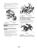
1.

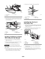
Install the frame assembly to the bagger cover with 2

locknuts (1/4 inch) (Fig. 5).

1

3

1849

2

Figure 5

1. Frame assembly
2. Bagger cover

3. Locknut, 1/4 inch

Summary of Contents for TimeCutter Z 79214

Page 1: ...Operator s Manual Original Instructions EN Form No 3329 278 Rev B 38I and 42I Twin Bagger TimeCutterR Z Attachment Model No 79214 Serial No 230000001 and Up Model No 79215 Serial No 230000001 and Up ...

Page 2: ... and produces safe products you are responsible for operating the product properly and safely Whenever you need service genuine Toro parts or additional information contact an Authorized Service Dealer or Toro Customer Service and have the model and serial numbers of your product ready Figure 1 illustrates the location of the model and serial numbers on the product 1 1375 Figure 1 1 Location of th...

Page 3: ...rd of hand do not remove the whole bagger from the machine open the bagger top and then remove the bag s from the bagger Do not remove the bagger top when it is closed open the bagger top and then remove it 93 1122 93 7316 International 1 Thrown object hazard stay a safe distance from the machine 2 Thrown object hazard mower keep the deflector in place 3 Cutting dismemberment of hand or foot stay ...

Page 4: ... the bagger assembly Pivot rod Nut 1 1 Installing the new pivot rod High lift blade 2 Installing the new blades for model 74214 only Chute Discharge tube 1 1 Installing the chute and discharge tube Decal 1 Installing the decal on International units only Installing the Front Weight The bagger adds a lot of weight to the rear of the machine and may cause an unstable condition which could result in ...

Page 5: ...ach Bracket 1 From the back of the mower slide the quick attach bracket along the outside of the rear frame 2 Align the holes in the rear frame and the bagger mounting bracket Fig 4 3 Secure the bagger mounting bracket to the rear frame with 4 bolts 3 8 x 1 inch 4 washers 3 8 inch and 4 locknuts 3 8 inch Fig 4 m 6626 3 5 2 2 1 4 Figure 4 1 Quick attach bracket 2 Bolts 3 8 x 1 inch 3 Locknut 3 8 in...

Page 6: ...gger top before you remove or install it on the quick attach bracket Caution 2 Install the bags by sliding the bag frame hooks onto the retaining brackets Fig 7 1 2 m 6627 Figure 7 1 Bag frame hook 2 Retaining bracket 3 Lower the bagger top onto the bags Then push down on both bag retainer handles until they lock on the bag frame Fig 8 1 m 6628 2 Figure 8 1 Bagger top 2 Bag retainer handles Instal...

Page 7: ...ade stiffener the curved washer cupped side toward the blade and the blade bolt Fig 11 Torque the blade bolt to 35 65 ft lb 47 88 N m 5 Repeat steps 1 through 4 for the opposite blade m 6430 1 2 5 3 4 Figure 11 1 Sail area of blade 2 Blade 3 Curved washer 4 Blade bolt 5 Blade stiffener Installing the Chute and Discharge Tube 1 Slide the chute into position with the rear hook around the deflector r...

Page 8: ... edges using overlapping strokes Removing the Bagger An uncovered discharge opening could allow the lawn mower to throw objects in the operator s or bystander s direction and result in serious injury Also contact with the blade could occur Never operate the lawn mower unless you install a cover plate a mulch plate or a grass chute and catcher Warning 1 Push on the tab on the chute and pull the dis...

Page 9: ...er with a nut 3 8 inch Fig 16 Important The grass deflector must be spring loaded in the down position Lift the deflector up to test that it snaps to the full down position m 6619 1 2 3 Figure 16 1 Grass deflector 2 Pivot rod 3 Nut 3 8 inch Operation Note Determine the left and right sides of the machine from the normal operating position To avoid personal injury follow these procedures Become fam...

Page 10: ...der the mower and entering the bagging system If enough air doesn t get under the mower the bagging system will plug Cutting Frequency Cut the grass often especially when it grows rapidly You will have to cut your grass twice if it gets excessively long refer to Bagging Long Grass page 11 Cutting Technique For best lawn appearance be sure to slightly overlap the mower into the previously cut area ...

Page 11: ...al side discharge feature of the mower Several hours later when the clippings are dry install the complete bagger attachment and vacuum up the grass clippings Signs of Plugging As you are bagging a small amount of grass clippings normally blow out the front of the mower An excessive amount of clippings blowing out indicates that the bags are full or the system is plugged Maintenance Note Determine...

Page 12: ...erator s manual for complete blade maintenance Caring for the Grass Bags Washing the grass bags is not recommended To prevent rapid deterioration of the bag material store the bags where they will dry completely after each use Cleaning the Bagger Attachment 1 After each use remove and wash the inside and outside of the bagger top discharge tube chute and the underside of the mower using water spra...

Page 13: ...13 ...

Page 14: ...14 ...

Page 15: ...15 ...

Page 16: ...216 6030 Canada customers Owner Responsibilities You must maintain your Toro Product by following the maintenance procedures described in the operator s manual Such routine maintenance whether performed by a dealer or by you is at your expense Items and Conditions Not Covered There is no other express warranty except for special emission system coverage on some products This express warranty does ...

Reviews: