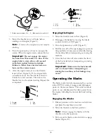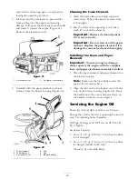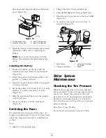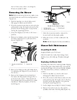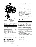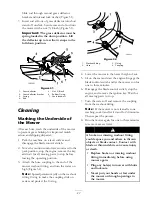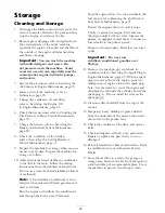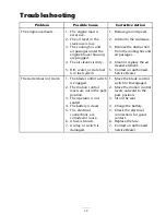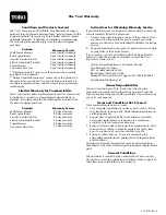
disconnect the charger leads from the battery
posts (Figure 34).
Figure 34
1. Positive battery post
3. Red (+) charger lead
2. Negative battery post
4. Black (-) charger lead
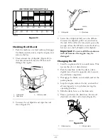
5. Install the battery in the machine and connect
the battery cables; refer to Installing the
Battery.
Note:
Do not run the machine with the
battery disconnected, electrical damage may
occur.
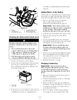
Installing the Battery
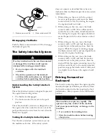
1. Position the battery in the tray with the
terminal posts away from the control panel
(Figure 32).
2. Install the positive (red) battery cable to the
positive (+) battery terminal.
3. Install the negative battery cable to the negative
(-) battery terminal.
4. Secure the cables with 2 bolts (1/4 x 3/4 inch),
washers (1/4 inch), and nuts (1/4 inch)
(Figure 32).
5. Slide the red terminal boot onto the positive
(red) battery post.
6. Secure the battery with the hold-down
(Figure 32).
Servicing the Fuses
The electrical system is protected by fuses. It
requires no maintenance; however, if a fuse blows,
check the component/circuit for a malfunction
or short.
Fuse:
•
Main F1-30 amp, blade-type
•
Charge Circuit F2-25 amp, blade-type
•
Optional Headlight Kit-10 amp, blade type
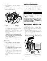
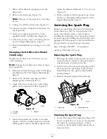
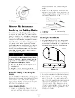
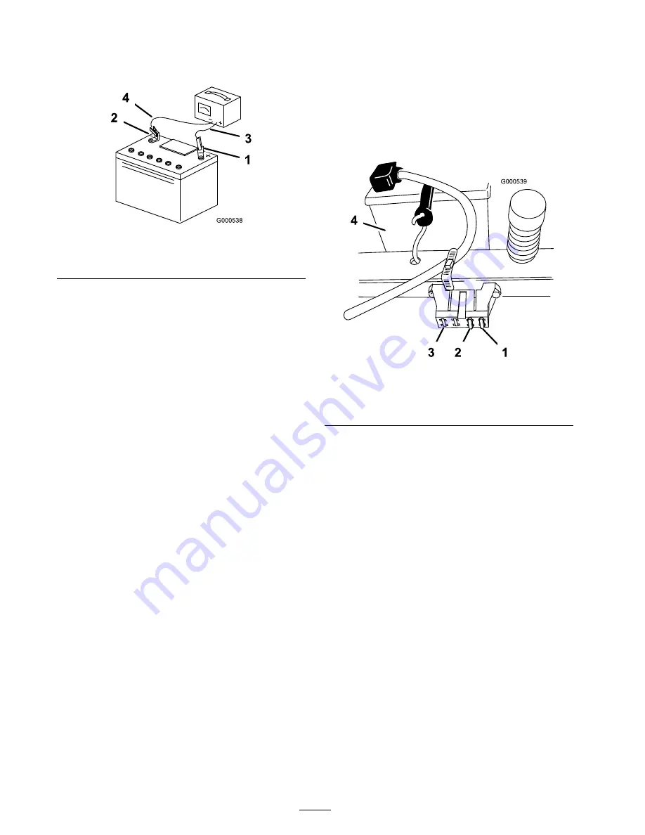
1. Raise the seat to gain access to the fuse holder
(Figure 35).
2. To replace a fuse, pull out on the fuse to
remove it (Figure 35).
Figure 35
1. Main-30 amp
3. For optional Headlight
Kit-10 amp
2. Charge circuit-25 amp
4. Battery
Drive System
Maintenance
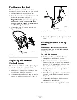
Checking the Tire Pressure
Maintain the air pressure in the front and rear
tires as specified. Uneven tire pressure can cause
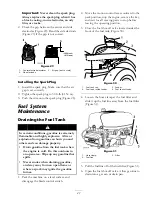
uneven cut. Check the pressure at the valve
stem after every 25 operating hours or monthly,
whichever occurs first (Figure 36). Check the
tires when they are cold to get the most accurate
pressure reading.
Rear Tires: 13 psi (90 kPa)
Front Tires (castor wheels): 35 psi (139 kPa)
30
Summary of Contents for TimeCutter Z380
Page 8: ...Slope Chart 8 ...

