background image

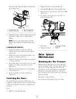
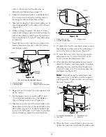
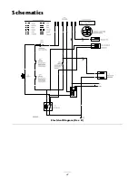
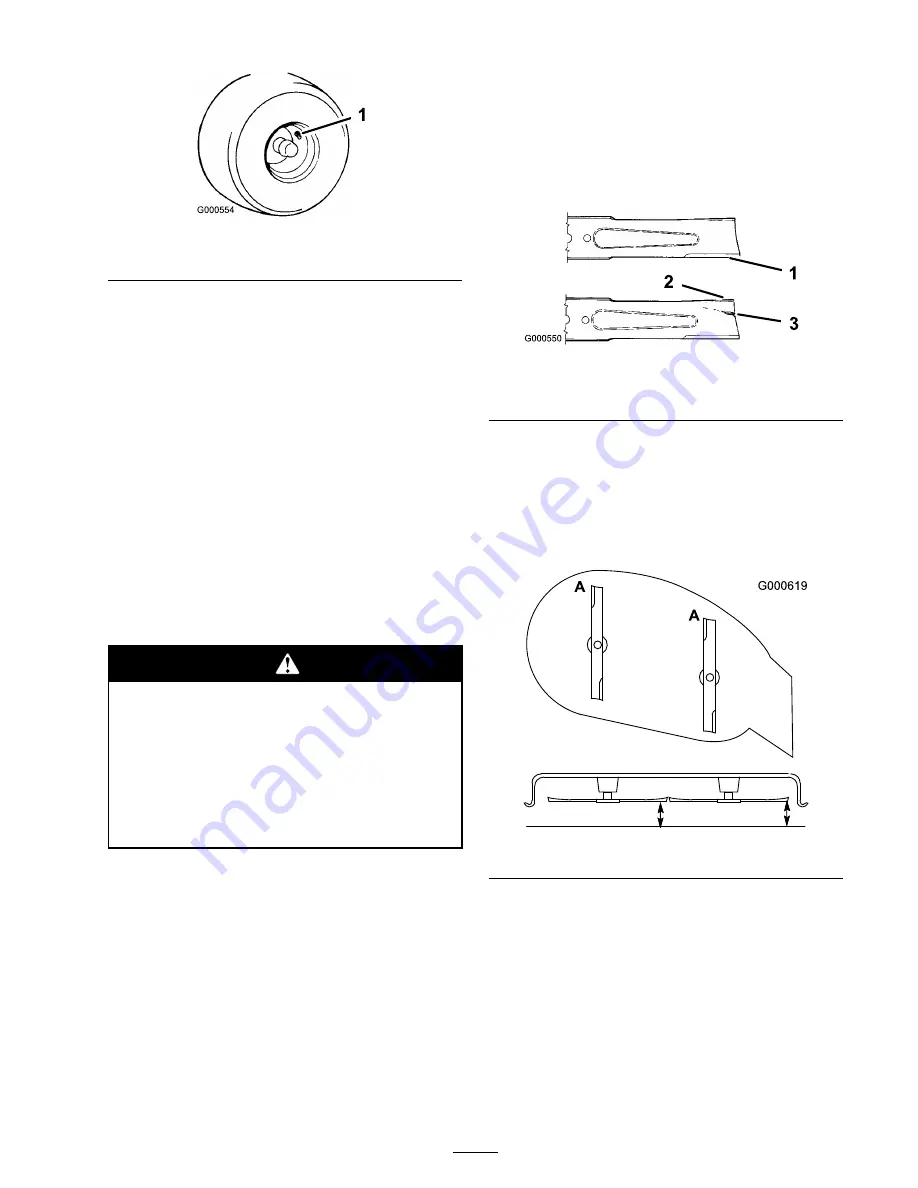
Figure 36

1. Valve stem

Mower Maintenance

Servicing the Cutting Blades

Maintain sharp blades throughout the cutting
season because sharp blades cut cleanly without
tearing or shredding the grass blades. Tearing and
shredding turns grass brown at the edges, which
slows growth and increases the chance of disease.

Check the cutter blades daily for sharpness, and
for any wear or damage. File down any nicks
and sharpen the blades as necessary. If a blade is
damaged or worn, replace it immediately with a
genuine Toro replacement blade. For convenient
sharpening and replacement, you may want to
keep extra blades on hand.

A worn or damaged blade can break, and a
piece of the blade could be thrown into the
operator’s or bystander’s area, resulting in
serious personal injury or death.

Inspect the blade periodically for wear
or damage.

Replace a worn or damaged blade.

Before Inspecting or Servicing the

Blades

Park the machine on a level surface, disengage the
blade control switch, and move the motion control
levers outward to the park position. Stop the
engine, remove the key, and disconnect the spark
plug wire(s) from the spark plug(s).

Inspecting the Blades

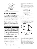
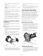
1. Inspect the cutting edges (Figure 37). If the

edges are not sharp or have nicks, remove and

sharpen the blades; refer to Sharpening the
Blades.

2. Inspect the blades, especially the curved area

(Figure 37). If you notice any damage, wear, or
a slot forming in this area (item 3 in Figure 37),
immediately install a new blade.

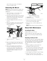
Figure 37

1. Cutting edge

3. Wear/slot forming

2. Curved area

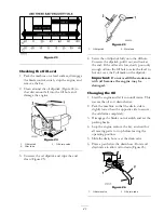
Checking for Bent Blades

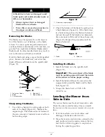
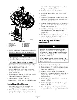
1. Rotate the blades until the ends face forward

and backward (Figure 38). Measure from a
level surface to the cutting edge, position

A

, of

the blades (Figure 38). Note this dimension.

Figure 38

2. Rotate the opposite ends of the blades forward.

3. Measure from a level surface to the cutting

edge of the blades at the same position as in
step 1. The difference between the dimensions
obtained in steps 1 and 2 must not exceed
1/8 inch (3 mm). If this dimension exceeds
1/8 inch (3 mm), the blade is bent and must be
replaced. Refer to Removing the Blades and
Installing the Blades.

31

Summary of Contents for TimeCutter Z380

Page 1: ...m No 3356 852 Rev C TimeCutter Z380 and Z420 Riding Mowers Model No 74419 Serial No 270000001 and Up Model No 74420 Serial No 270000001 and Up Register your product at www Toro com Original Instructions EN ...

Page 2: ...or death if you do not follow the recommended precautions Figure 2 1 Safety alert symbol This manual uses two other words to highlight information Important calls attention to special mechanical information and Note emphasizes general information worthy of special attention Contents Introduction 2 Safety 4 Safe Operation Practices for Ride on riding Rotary Lawnmower Machines 4 Safe Operating Pract...

Page 3: ...ystem Maintenance 28 Servicing the Battery 28 Servicing the Fuses 30 Drive System Maintenance 30 Checking the Tire Pressure 30 Mower Maintenance 31 Servicing the Cutting Blades 31 Leveling the Mower from Side to Side 32 Adjusting the Front to Rear Blade Slope 33 Removing the Mower 35 Mower Belt Maintenance 35 Installing the Mower 36 Replacing the Grass Deflector 36 Cleaning 37 Washing the Underside...

Page 4: ...achines control of a ride on machine sliding on a slope will not be regained by the application of the brake The main reasons for loss of control are insufficient wheel grip being driven too fast inadequate braking the type of machine is unsuitable for its task lack of awareness of the effect of ground conditions especially slopes incorrect hitching and load distribution Preparation While mowing al...

Page 5: ...ove the key Disengage drive to attachments stop the engine and disconnect the spark plug wire s or remove the ignition key before clearing blockages or unclogging chute before checking cleaning or working on the lawnmower after striking a foreign object Inspect the lawnmower for damage and make repairs before restarting and operating the equipment if the machine starts to vibrate abnormally check ...

Page 6: ... grass can hide obstacles Watch for ditches holes rocks dips and rises that change the operating angle as rough terrain could overturn the machine Avoid sudden starts when mowing uphill because the mower may tip backwards Be aware that loss of traction may occur going downhill Weight transfer to the front wheels may cause drive wheels to slip and cause loss of braking and steering Always avoid sud...

Page 7: ...l machines per EN 1032 Model 74420 This unit has an equivalent continuous A weighted hand arm vibration level of 4 66 m s2 based on measurements of identical machines per EN 1033 This unit has an equivalent continuous A weighted whole body vibration level of 14 m s2 based on measurements of identical machines per EN 1032 7 ...

Page 8: ...Slope Chart 8 ...
Page 9: ...lace 2 Cutting dismemberment hazard of hand or foot mower blade stay away from moving parts 93 7317 1 Thrown object hazard keep bystanders a safe distance from the machine 2 Thrown object hazard mower keep the de ector in place 3 Cutting dismemberment of hand or foot stay away from moving parts Manufacturer s Mark 1 Indicates the blade is identi ed as a part from the original machine manufacturer ...

Page 10: ...re every 25 operating hours 3 Grease every 25 operating hours 4 Engine 106 8742 1 Parking brake 106 8743 1 Height of cut Battery Symbols Some or all of these symbols are on your battery 1 Explosion hazard 6 Keep bystanders a safe distance from the battery 2 No re open ame or smoking 7 Wear eye protection explosive gases can cause blindness and other injuries 3 Caustic liquid chemical burn hazard 8...

Page 11: ...oss of traction control hazard slopes loss of traction control on a slope disengage the blade control switch PTO proceed off the slope slowly 5 Crushing dismemberment hazard of bystanders reversing crushing dismemberment hazard of bystanders do not carry passengers look behind and down when reversing 6 Tipping hazard do not mow up and down slopes only mow across slopes less than 15 degrees avoid s...

Page 12: ...Product Overview Figure 3 1 Seat 4 Height of cut lever 7 Front caster wheel 10 Anti scalp roller 2 Control levers 5 Mower deck 8 Rear drive wheel 3 Control panel 6 Footrest 9 Cup holder 12 ...

Page 13: ...f cut lever allows the operator to lower and raise the deck from the seated position When the lever is moved up toward the operator the deck is raised from the ground and when moved down away from the operator it is lowered to the ground Only adjust the height of cut while machine is not moving Figure 4 Ignition Switch The ignition switch has three positions Off Run and Start The key will turn to ...

Page 14: ...e minimum Leaded regular gasoline may be used if unleaded regular is not available Important Never use methanol gasoline containing methanol or gasohol containing more than 10 ethanol because the fuel system could be damaged Do not mix oil with gasoline In certain conditions gasoline is extremely flammable and highly explosive A fire or explosion from gasoline can burn you and others and can damage ...

Page 15: ...e machine to provide the following benefits Keeps gasoline fresh during storage of 90 days or less For longer storage it is recommended that the fuel tank be drained Cleans the engine while it runs Eliminates gum like varnish buildup in the fuel system which causes hard starting Important Do not use fuel additives containing methanol or ethanol Add the correct amount of gas stabilizer conditioner t...

Page 16: ...r to Fast Figure 8 2 Disengage the blades by moving the blade control switch to Off Figure 7 3 Turn the ignition key to Off Figure 9 4 Pull the wire off of the spark plug s to prevent the possibility of someone accidentally starting the machine before transporting or storing the machine 5 Close the fuel shut off valve under the front of the fuel tank before transporting or storing the machine Impo...

Page 17: ...ition and move the blade control switch to On Try starting the engine the engine should not crank 2 While sitting on the seat move the blade control switch to Off Move either motion control lever to the center unlocked position Try starting the engine the engine should not crank Repeat with the other motion control lever 3 While sitting on the seat move the blade control switch to Off and lock the...

Page 18: ...Figure 11 To stop push the motion control levers to neutral Stopping the Machine To stop the machine move the motion control levers to neutral and outward to the park position disengage the blade control switch ensure the throttle is in the fast position and turn the ignition key to off Remember to remove the key from the ignition switch Children or bystanders may be injured if they move or attemp...

Page 19: ...t Figure 14 2 Move the control lever to the next set of holes Secure the lever with the 2 bolts Figure 14 Figure 14 1 Control lever 3 Control arm shaft 2 Bolt 3 Repeat the adjustment for the opposite control lever Pushing the Machine by Hand Important Always push the machine by hand Never tow the machine because damage may occur To Push the Machine 1 Park the machine on a level surface and disenga...

Page 20: ...ctor from the mower because the grass deflector routes material down toward the turf If the grass deflector is ever damaged replace it immediately Never put your hands or feet under the mower Never try to clear discharge area or mower blades unless you move the blade control switch to Off and rotate the ignition key to Off Also remove the key and pull the wire off the spark plug s Operating Tips Fas...

Page 21: ...r normal setting When Stopping If the machine s forward motion must be stopped while mowing a clump of grass clippings may drop onto your lawn To avoid this move onto a previously cut area with the blades engaged Keep the Underside of the Mower Clean Clean clippings and dirt from the underside of the mower after each use If grass and dirt build up inside the mower cutting quality will eventually b...

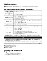
Page 22: ...ir lter element more often in dirty or dusty conditions Change the oil lter model 74420 only Replace spark plug Replace fuel lter Before storage Drain the fuel tank Charge the battery and disconnect battery cables Perform all maintenance procedures listed above before storage Paint any chipped surfaces Important Refer to your engine operator s manual for additional maintenance procedures If you le...

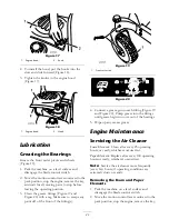
Page 23: ...to scrape any paint off of the front of the fitting s Figure 19 1 Front caster tire Figure 20 4 Connect a grease gun to each fitting Figure 19 and Figure 20 Pump grease into the fittings until grease begins to ooze out of the bearings 5 Wipe up any excess grease Engine Maintenance Servicing the Air Cleaner Foam Element Clean after every 25 operating hours or yearly whichever occurs first Paper Element...

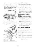
Page 24: ...ot clean or oil the paper element Replace the paper element if it is damaged or cannot be cleaned thoroughly Installing the Foam and Paper Elements Important To prevent engine damage always operate the engine with the complete foam and paper air cleaner assembly installed 1 Place the foam element and paper element into the blower housing Note Make sure that the rubber seal is flat against the air c...

Page 25: ...nough oil into the fill hole to raise the level to but not over the Full mark on the dipstick Important Do not overfill the crankcase with oil because the engine may be damaged Changing the Oil 1 Start the engine and let it run until warm This warms the oil so it drains better 2 Park the machine so that the drain side is slightly lower than the opposite side to assure the oil drains completely 3 Dis...

Page 26: ... gasket contacts the filter adapter then tighten the filter an additional 1 2 to 3 4 turn Figure 27 5 Fill the crankcase with the proper type of new oil refer to Changing and Draining the Oil in Engine Maintenance page 23 Servicing the Spark Plug Replace the spark plug after every 100 operating hours Make sure that the air gap between the center and side electrodes is correct before installing the s...

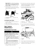
Page 27: ...asoline from the fuel tank when the engine is cold Do this outdoors in an open area Wipe up any gasoline that spills Never smoke when draining gasoline and stay away from an open flame or where a spark may ignite the gasoline fumes 1 Park the machine on a level surface and disengage the blade control switch 2 Move the motion control levers outward to the park position stop the engine remove the key...

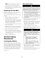
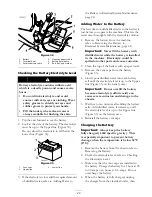
Page 28: ...n them with a solution of four parts water and one part baking soda Apply a light coating of grease to the battery terminals to prevent corrosion Voltage 12 V Removing the Battery Battery terminals or metal tools could short against metal machine components causing sparks Sparks can cause the battery gasses to explode resulting in personal injury When removing or installing the battery do not allo...

Page 29: ...Electrical System Maintenance page 28 Important Never fill the battery with distilled water while the battery is installed in the machine Electrolyte could be spilled on other parts and cause corrosion 2 Clean the top of the battery with a paper towel 3 Remove the vent caps from the battery Figure 33 4 Slowly pour distilled water into each battery cell until the electrolyte level is up to the Upper...

Page 30: ...st 6 Secure the battery with the hold down Figure 32 Servicing the Fuses The electrical system is protected by fuses It requires no maintenance however if a fuse blows check the component circuit for a malfunction or short Fuse Main F1 30 amp blade type Charge Circuit F2 25 amp blade type Optional Headlight Kit 10 amp blade type 1 Raise the seat to gain access to the fuse holder Figure 35 2 To rep...

Page 31: ...e control switch and move the motion control levers outward to the park position Stop the engine remove the key and disconnect the spark plug wire s from the spark plug s Inspecting the Blades 1 Inspect the cutting edges Figure 37 If the edges are not sharp or have nicks remove and sharpen the blades refer to Sharpening the Blades 2 Inspect the blades especially the curved area Figure 37 If you no...

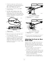
Page 32: ... is removed from both cutting edges Figure 40 1 Sharpen at original angle 2 Check the balance of the blade by putting it on a blade balancer Figure 41 If the blade stays in a horizontal position the blade is balanced and can be used If the blade is not balanced file some metal off the end of the sail area only Figure 40 Repeat this procedure until the blade is balanced Figure 41 1 Blade 2 Balancer ...

Page 33: ...height and a rear hole raises its height Adjust both sides as required Figure 43 42 inch leveler bracket shown 1 Hairpin cotter and washer 3 Front hole 2 Leveling bracket 4 Rear hole Figure 44 38 inch leveler bracket shown 1 Hairpin cotter and washer 3 Front hole 2 Leveling bracket 4 Rear hole 8 Check the front to rear blade slope refer to Adjusting the Front to Rear Blade Slope Adjusting the Fron...

Page 34: ... Figure 46 10 Measure from the tip of the front blade to the flat surface and the tip of the rear blade to the flat surface Figure 46 If the front blade tip is not 1 16 5 16 inch 1 6 7 9 mm lower than the rear blade tip adjust the front locknuts Figure 46 1 Blades front to rear 3 Measure here 2 Outside cutting edges 11 To adjust the front to rear blade slope remove the locknuts and then rotate the a...

Page 35: ...re installation Slide the brackets off of the mounting pin Figure 49 38 inch leveler bracket shown 1 Leveling bracket 3 Adjusting rod 2 Hairpin cotter and washer 7 Slide the mower rearward to remove the mower belt from the engine pulley 8 Slide the mower out from underneath the machine Note Retain all parts for future installation Mower Belt Maintenance Inspecting the Belts Inspect all belts every...

Page 36: ...r to the lowest position 5 Attach the adjusting rod to the machine with the washer and hairpin cotter Figure 49 on each side of the mower 6 Slide the leveling brackets onto the mounting pins and secure them with the washers and hairpin cotters Figure 49 7 Attach the front support rods to the machine with the clevis pins and hairpin cotters Figure 48 8 Install the mower belt onto the engine pulley ...

Page 37: ...the mower washout fitting and turn the water on high Figure 52 Note Spread petroleum jelly on the washout fitting O ring to make the coupling slide on easier and protect the O ring Figure 52 1 Washout tting 3 O ring 2 Hose 4 Coupling 4 Lower the mower to the lowest height of cut 5 Sit on the seat and start the engine Engage the blade control switch and let the mower run for one to three minutes 6 Di...

Page 38: ...stabilizer conditioner is most effective when mixed with fresh gasoline and used at all times Run the engine to distribute the conditioned fuel through the fuel system 5 minutes Stop the engine allow it to cool and drain the fuel tank refer to Draining the Fuel Tank in Fuel System Maintenance page 27 Restart the engine and run it until it stops Choke or prime the engine Start and run the engine un...

Page 39: ...irt water or stale fuel is in fuel system 5 Contact an Authorized Service Dealer 1 The blade control switch is engaged 1 Move the blade control switch to Disengaged 2 The motion control levers are not in the park position 2 Move the motion control levers outward to the park position 3 The operator is not seated 3 Sit on the seat 4 The battery is dead 4 Charge the battery 5 The electrical connectio...

Page 40: ...low 10 Add oil to the crankcase 1 The engine load is excessive 1 Reduce ground speed 2 The air cleaner is dirty 2 Clean the air cleaner element 3 The oil level in the crankcase is low 3 Add oil to the crankcase 4 The cooling ns and air passages under the engine blower housing are plugged 4 Remove the obstruction from the cooling ns and air passages 5 The spark plug s is pitted fouled or the gap is...

Page 41: ... the blade s 2 A cutting blade s is are bent 2 Install a new cutting blade s 3 The mower is not level 3 Level the mower from side to side and front to rear 4 An anti scalp wheel is not set correctly 4 Adjust the anti scalp wheel height 5 The underside of the mower is dirty 5 Clean the underside of the mower 6 The tire pressure is incorrect 6 Adjust the tire pressure Uneven cutting height 7 A blade...

Page 42: ...Schematics Electrical Diagram Rev B 42 ...

Page 43: ... A Italy 39 0331 853611 Irriamc Portugal 351 21 238 8260 Jean Heybroek b v Netherlands 31 30 639 4611 Lely U K Limited United Kingdom 44 1480 226 800 Maquiver S A Columbia 57 1 236 4079 Maruyama Mfg Co Inc Japan 81 3 3252 2285 Metra Kft Hungary 36 1 326 3880 Mount eld a s Czech Republic 420 255 704 220 Munditol S A Argentina 54 11 4 821 9999 Oslinger Turf Equipment SA Ecuador 593 4 239 6970 Oy Hak...

Page 44: ...f the product If for any reason it is impossible for you to contact your seller you may contact any Toro Authorized Distributor to arrange service 2 Bring the product and your proof of purchase sales receipt to your seller or the Service Dealer If for any reason you are dissatis ed with the Service Dealer s analysis or with the assistance provided contact the Toro importer or contact us at Custome...

Reviews: