Premaintenance
Procedures
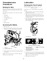
Raising the Seat
Make sure the motion control levers are locked in the
park position. Lift the seat forward and lower it to the
floor board.
The following components can be accessed by raising
the seat:
•
Serial plate
•
Service decal
•
Seat adjustment knob
•
Fuel filter
•
Fuses
•
Battery cables
Accessing the Battery
1. Raise the seat.
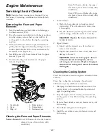
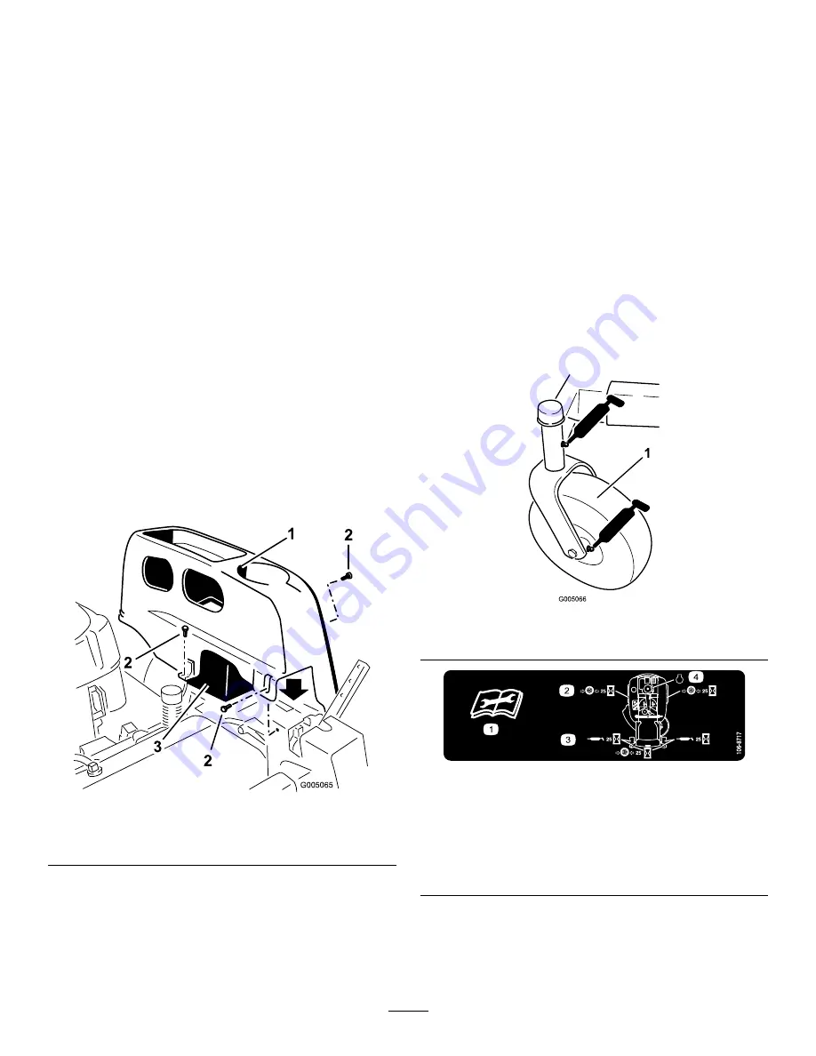
2. Remove the TORX
®
head fasteners (25) securing
the left cover to the frame as shown in Figure 19.
2
3
G005065
1
2
2
2
3
Figure 19
1.
Left cover
3.
Battery
2.
Torx head fasteners (25)
3. Lift the plastic cover away from the machine. Retain
all fasteners.
Replace the cover and secure it to the frame using the
fasteners removed previously.
Lubrication
Greasing the Front Casters
Service Interval:
Every 25 hours—Grease all
lubrication points.
Grease Type: No. 2 General Purpose Lithium Base
Grease
1. Park the machine on a level surface and disengage
the blade control switch.
2. Move the motion control levers outward to the
park position, stop the engine, remove the key, and
wait for all moving parts to stop before leaving the
operating position.
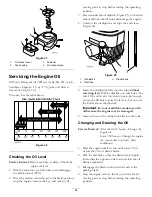
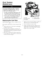
3. Clean the grease fittings (Figure 20 and Figure 21)
with a rag. Make sure to scrape any paint off of the
front of the fitting(s).
G005066
1
Figure 20
1.
Front caster tire
Figure 21
Located on the seat pan underside
1.
Read the instructions
before servicing or
performing maintenance.
3.
Grease every 25 operating
hours.
2.
Check tire pressure every
25 operating hours.
4.
Engine
4. Connect a grease gun to each fitting (Figure 20 and
Figure 21). Pump grease into the fittings until grease
begins to ooze out of the bearings.
5. Wipe up any excess grease.
22


