Controls
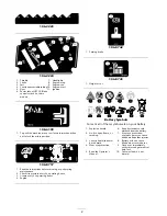
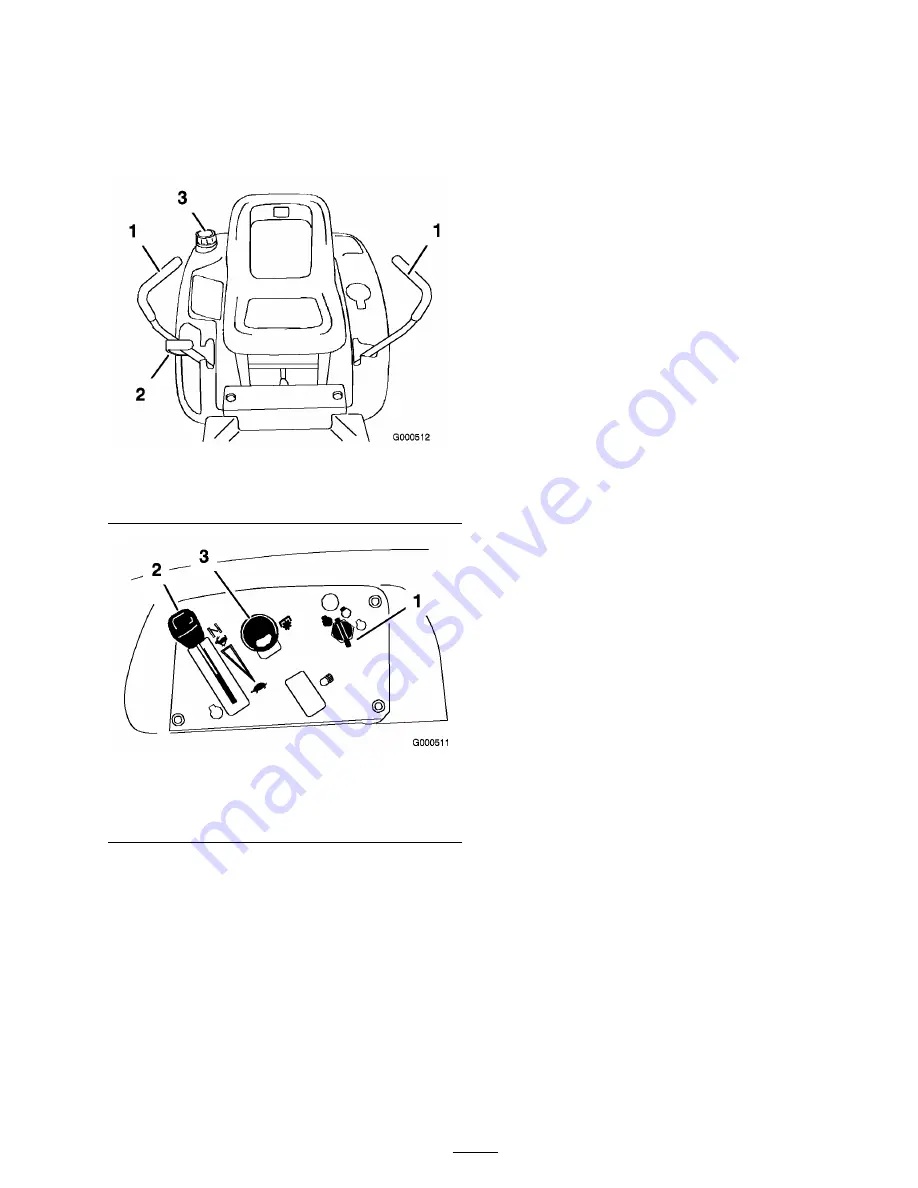
Become familiar with all of the controls Figure 5
and Figure 4 before you start the engine and
operate the machine.
Figure 4
1. Motion control lever
3. Gas tank cap
2. Height-of-cut lever
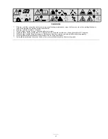
Figure 5
1. Ignition switch
3. Blade control switch
(power take-off)
2. Throttle/Choke
Parking Brake
The parking brake is automatically set when the
motion control levers are in the brake position.
Always position the motion control levers into the
brake position when you stop the machine or leave
it unattended.
11
Summary of Contents for TimeCutter Z530
Page 41: ...Schematics Electrical Diagram Rev B 41 ...
Page 42: ......
Page 43: ......
Page 44: ......


