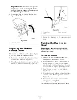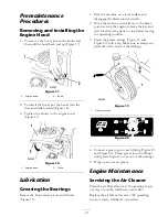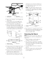
Figure 15
1. Bypass levers
3. Lever position for operating
the machine
2. Lever position for pushing
the machine
To Operate the Machine
Move the bypass levers to the inside and pull them
rearward, to the end the slot (Figure 15).
Note:
The machine will not drive unless the
bypass levers are disengaged.
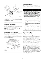
Adjusting the Footrest
The footrest can be adjusted forward or backward
for maximum operator comfort.
Lift up the footrest and place the rods in the same
hole positions (Figure 16).
Figure 16
1. Footrest
3. Hole positions
2. Rod
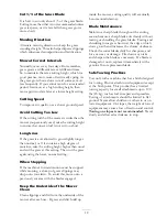
Side Discharge
The mower has a hinged grass deflector that
disperses clippings to the side and down toward
the turf.
Without the grass deflector, discharge
cover, or complete grass catcher assembly
mounted in place, you and others are
exposed to blade contact and thrown debris.
Contact with rotating mower blade(s) and
thrown debris will cause injury or death.
•
Never remove the grass deflector from
the mower because the grass deflector
routes material down toward the turf.
If the grass deflector is ever damaged,
replace it immediately.
•
Never put your hands or feet under the
mower.
•
Never try to clear discharge area or
mower blades unless you move the blade
control switch to Off and rotate the
ignition key to Off. Also remove the key
and pull the wire off the spark plug(s).
Operating Tips
Fast Throttle Setting
For best mowing and maximum air circulation,
operate the engine at the Fast position. Air is
required to thoroughly cut grass clippings, so
do not set the height-of-cut so low as to totally
surround the mower by uncut grass. Always try to
have one side of the mower free from uncut grass,
which allows air to be drawn into the mower.
Cutting a Lawn for the First Time
Cut grass slightly longer than normal to ensure
that the cutting height of the mower does not
scalp any uneven ground. However, the cutting
height used in the past is generally the best one to
use. When cutting grass longer than six inches tall,
you may want to cut the lawn twice to ensure an
acceptable quality of cut.
18
Summary of Contents for TimeCutter Z530
Page 41: ...Schematics Electrical Diagram Rev B 41 ...
Page 42: ......
Page 43: ......
Page 44: ......

