background image

Premaintenance

Procedures

Removing and Installing the

Engine Hood

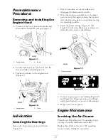
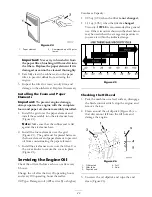
1. To remove the hood, loosen the knobs and

then pull the hood back and up (Figure 17).

Figure 17

1. Engine hood

2. Knob

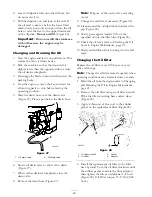
2. To install the hood, put the hooks into the

slots and slide forward (Figure 18).

3. Tighten the knobs in the engine hood

(Figure 17).

Figure 18

1. Engine hood

2. Hook

Lubrication

Greasing the Bearings

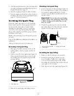
Grease the front caster pivots and wheels
(Figure 19).

1. Park the machine on a level surface and

disengage the blade control switch.

2. Move the motion control levers to the brake

position, stop the engine, remove the key, and
wait for all moving parts to stop before leaving
the operating position.

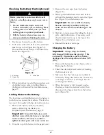
3. Clean the grease fittings (Figure 19 and

Figure 20) with a rag. Make sure to scrape any
paint off of the front of the fitting(s).

Figure 19

1. Front caster tire

Figure 20

4. Connect a grease gun to each fitting (Figure 19

and Figure 20). Pump grease into the fittings
until grease begins to ooze out of the bearings.

5. Wipe up any excess grease.

Engine Maintenance

Servicing the Air Cleaner

Clean the air filter after every 50 operating hours
or every 3 months, whichever occurs first.

Replace the air filter after every 300 operating
hours or yearly, whichever occurs first.

21

Summary of Contents for TimeCutter Z530

Page 1: ...Form No 3354 901 Rev A TimeCutter Z530 Riding Mowers Model No 74425 Serial No 260000001 and Up Register your product at www Toro com Original Instructions EN ...

Page 2: ...o not follow the recommended precautions Figure 2 1 Safety alert symbol This manual uses two other words to highlight information Important calls attention to special mechanical information and Note emphasizes general information worthy of special attention Contents Introduction 2 Safety 4 Safe Operation Practices for Ride on riding Rotary Lawnmower Machines 4 Safe Operating Practices 4 Toro Ridin...

Page 3: ...ystem Maintenance 27 Servicing the Battery 27 Servicing the Fuses 29 Drive System Maintenance 29 Checking the Tire Pressure 29 Mower Maintenance 30 Servicing the Cutting Blades 30 Leveling the Mower from Side to Side 31 Adjusting the Front to Rear Blade Slope 32 Removing the Mower 33 Mower Belt Maintenance 34 Installing the Mower 35 Replacing the Grass Deflector 35 Cleaning 36 Washing the Underside...

Page 4: ...achines control of a ride on machine sliding on a slope will not be regained by the application of the brake The main reasons for loss of control are insufficient wheel grip being driven too fast inadequate braking the type of machine is unsuitable for its task lack of awareness of the effect of ground conditions especially slopes incorrect hitching and load distribution Preparation While mowing al...

Page 5: ...emove the key Disengage drive to attachments stop the engine and disconnect the spark plug wire s or remove the ignition key before clearing blockages or unclogging chute before checking cleaning or working on the lawnmower after striking a foreign object Inspect the lawnmower for damage and make repairs before restarting and operating the equipment if the machine starts to vibrate abnormally chec...

Page 6: ... banks or water Reduce speed and use extreme caution on slopes Remove or mark obstacles such as rocks tree limbs etc from mowing area Tall grass can hide obstacles Watch for ditches holes rocks dips and rises that change the operating angle as rough terrain could overturn the machine Avoid sudden starts when mowing uphill because the mower may tip backwards Be aware that loss of traction may occur...

Page 7: ...lace 2 Cutting dismemberment hazard of hand or foot mower blade stay away from moving parts 93 7010 1 Thrown object hazard keep bystanders a safe distance from the machine 2 Thrown object hazard mower keep the de ector in place 3 Cutting dismemberment of hand or foot stay away from moving parts Manufacturer s Mark 1 Indicates the blade is identi ed as a part from the original machine manufacturer ...

Page 8: ...re every 25 operating hours 3 Grease every 25 operating hours 4 Engine 106 8742 1 Parking brake 106 8743 1 Height of cut Battery Symbols Some or all of these symbols are on your battery 1 Explosion hazard 6 Keep bystanders a safe distance from the battery 2 No re open ame or smoking 7 Wear eye protection explosive gases can cause blindness and other injuries 3 Caustic liquid chemical burn hazard 8...

Page 9: ...wn object hazard mower keep the de ector in place 4 Tipping hazard slopes greater than 12 5 degrees do not drive the machine on a slope greater than 12 5 degrees 5 Thrown object hazard keep bystanders a safe distance from the machine and pick up debris before operating 6 Crushing dismemberment hazard of bystanders do not carry passengers 7 Cutting dismemberment hazard of hand or foot mower blade s...

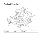
Page 10: ...Product Overview Figure 3 1 Seat 4 Height of cut lever 7 Front caster wheel 10 Anti scalp roller 2 Control levers 5 Mower deck 8 Rear drive wheel 3 Control panel 6 Footrest 9 Cup holder 10 ...

Page 11: ...lever 3 Gas tank cap 2 Height of cut lever Figure 5 1 Ignition switch 3 Blade control switch power take off 2 Throttle Choke Parking Brake The parking brake is automatically set when the motion control levers are in the brake position Always position the motion control levers into the brake position when you stop the machine or leave it unattended 11 ...

Page 12: ...ne minimum Leaded regular gasoline may be used if unleaded regular is not available Important Never use methanol gasoline containing methanol or gasohol containing more than 10 ethanol because the fuel system could be damaged Do not mix oil with gasoline In certain conditions gasoline is extremely flammable and highly explosive A fire or explosion from gasoline can burn you and others and can damage...

Page 13: ...nditioner in the machine to provide the following benefits Keeps gasoline fresh during storage of 90 days or less For longer storage it is recommended that the fuel tank be drained Cleans the engine while it runs Eliminates gum like varnish buildup in the fuel system which causes hard starting Important Do not use fuel additives containing methanol or ethanol Add the correct amount of gas stabilize...

Page 14: ... moving the blade control switch to Off Figure 7 3 Turn the ignition key to Off Figure 9 4 Pull the wire off of the spark plug s to prevent the possibility of someone accidentally starting the machine before transporting or storing the machine 5 Close the fuel shut off valve under the front of the fuel tank before transporting or storing the machine Important Make sure the fuel shut off valve is c...

Page 15: ...he blade control switch to Off Move either motion control lever to the center unlocked position Try starting the engine the engine should not crank Repeat with the other motion control lever 3 While sitting on the seat move the blade control switch to Off and lock the motion control levers in neutral Start the engine While the engine is running engage the blade control switch and rise slightly fro...

Page 16: ...engage the blade control switch ensure the throttle is in the fast position and turn the ignition key to off Remember to remove the key from the ignition switch Children or bystanders may be injured if they move or attempt to operate the mower while it is unattended Always remove the ignition key and move the motion control levers to the brake position when leaving the machine unattended even if j...

Page 17: ...rol lever 3 Control arm shaft 2 Bolt 3 Repeat the adjustment for the opposite control lever Pushing the Machine by Hand Important Always push the machine by hand Never tow the machine because damage may occur To Push the Machine 1 Park the machine on a level surface and disengage the blade control switch 2 Move the motion control levers outward to engage the parking brake stop the engine remove th...

Page 18: ...ctor from the mower because the grass deflector routes material down toward the turf If the grass deflector is ever damaged replace it immediately Never put your hands or feet under the mower Never try to clear discharge area or mower blades unless you move the blade control switch to Off and rotate the ignition key to Off Also remove the key and pull the wire off the spark plug s Operating Tips Fas...

Page 19: ...r normal setting When Stopping If the machine s forward motion must be stopped while mowing a clump of grass clippings may drop onto your lawn To avoid this move onto a previously cut area with the blades engaged Keep the Underside of the Mower Clean Clean clippings and dirt from the underside of the mower after each use If grass and dirt build up inside the mower cutting quality will eventually b...

Page 20: ...the engine under heavy load or in high temperatures Change the oil lter Check the spark plug Every 300 hours Clean the combustion chamber Yearly or before storage Clean the cooling system more often in dirty or dusty conditions Change the air lter more often in dirty or dusty conditions Replace spark plug Clean the fuel tank and lter Check the fuel line replace if necessary Replace fuel lter Charg...

Page 21: ...the motion control levers to the brake position stop the engine remove the key and wait for all moving parts to stop before leaving the operating position 3 Clean the grease fittings Figure 19 and Figure 20 with a rag Make sure to scrape any paint off of the front of the fitting s Figure 19 1 Front caster tire Figure 20 4 Connect a grease gun to each fitting Figure 19 and Figure 20 Pump grease into t...

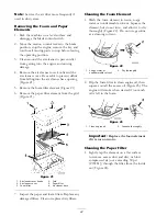
Page 22: ...r knobs 4 Grid 2 Air cleaner cover 5 Paper lter 3 Foam lter 6 Air cleaner base 7 Inspect the paper and foam filters Replace any damaged filters Clean or replace dirty filters Cleaning the Foam Element 1 Wash the foam element in warm soapy water or nonflammable solvent Squeeze the element but do not twist and allow it to dry thoroughly Figure 22 Do not use gasoline as a cleaning solvent Figure 22 1 Soa...

Page 23: ...ent and paper element to prevent oil from contaminating the paper element 3 Install the air cleaner cover over the filter Use the cover knobs to secure the cover in place Figure 21 Servicing the Engine Oil Check the oil level before each use or after every 8 hours Change the oil after the first 20 operating hours and every 100 operating hours thereafter Oil Type Detergent oil API service SJ or highe...

Page 24: ...ose the drain valve 8 Remove the drain hose Figure 27 Note Dispose of the used oil at a recycling center 9 Change the oil filter if necessary Figure 28 10 Clean around the oil dipstick and unscrew the cap Figure 26 11 Slowly pour approximately 80 of the specified oil into the filler tube Figure 26 12 Check the oil level refer to Checking the Oil Level in Engine Maintenance page 21 13 Slowly add addit...

Page 25: ... wire off of the spark plug Figure 29 Clean around the spark plug to prevent dirt from falling into the engine and potentially causing damage Figure 29 1 Spark plug wire 3 Remove the spark plug and sealing washer Checking the Spark Plug 1 Look at the center of the spark plug Figure 30 If you see light brown or gray on the insulator the engine is operating properly A black coating on the insulator ...

Page 26: ...ter 2 Fuel line 5 Pull the fuel line off of the fuel filter Figure 31 6 Open the fuel shut off valve Allow gasoline to drain into a gas can or drain pan Note Now is the best time to install a new fuel filter because the fuel tank is empty 7 Install the fuel line onto the fuel filter Slide the hose clamp close to the fuel filter to secure the fuel line Figure 31 Replacing the Fuel Filter Replace the fu...

Page 27: ...hine on a level surface and disengage the blade control switch 2 Move the motion control levers to the brake position stop the engine remove the key and wait for all moving parts to stop before leaving the operating position 3 Tip the seat forward to see the battery 4 Disconnect the negative black ground cable from the battery post Figure 32 Incorrect battery cable routing could damage the machine...

Page 28: ...e the battery is installed in the machine Electrolyte could be spilled on other parts and cause corrosion 2 Clean the top of the battery with a paper towel 3 Remove the vent caps from the battery Figure 33 4 Slowly pour distilled water into each battery cell until the electrolyte level is up to the Upper line Figure 33 on the battery case Important Do not overfill the battery because electrolyte su...

Page 29: ...e hold down Figure 32 Servicing the Fuses The electrical system is protected by fuses It requires no maintenance however if a fuse blows check the component circuit for a malfunction or short Fuse Main F1 30 amp blade type Charge Circuit F2 25 amp blade type Optional Headlight Kit 10 amp blade type 1 Raise the seat to gain access to the fuse holder Figure 35 2 To replace a fuse pull out on the fus...

Page 30: ...blade control switch and move the motion control levers to the brake position Stop the engine remove the key and disconnect the spark plug wire s from the spark plug s Inspecting the Blades 1 Inspect the cutting edges Figure 37 If the edges are not sharp or have nicks remove and sharpen the blades refer to Sharpening the Blades 2 Inspect the blades especially the curved area Figure 37 If you notic...

Page 31: ...rial is removed from both cutting edges Figure 40 1 Sharpen at original angle 2 Check the balance of the blade by putting it on a blade balancer Figure 41 If the blade stays in a horizontal position the blade is balanced and can be used If the blade is not balanced file some metal off the end of the sail area only Figure 40 Repeat this procedure until the blade is balanced Figure 41 1 Blade 2 Balan...

Page 32: ...ade Slope Adjusting the Front to Rear Blade Slope Check the front to rear blade level any time you install the mower If the front of the mower is more than 5 16 inch 7 9 mm lower than the rear of the mower adjust the blade level using the following instructions 1 Park the machine on a level surface and disengage the blade control switch 2 Move the motion control levers to the brake position stop t...

Page 33: ...evenly check the front to rear slope again Continue adjusting the nuts until the front blade tip is 1 16 5 16 inch 1 6 7 9 mm lower than the rear blade tip Figure 46 Note After adjusting the adjustment nuts make sure there is no slack in either support rod Figure 47 Tighten either one to remove the slack Figure 46 Figure 46 1 Locknut and adjusting nut 3 Adjustment nut 2 Front tire 4 Lock nut 14 Wh...

Page 34: ... the belts for cracks frayed edges burn marks or any other damage Replace damaged belts Replacing the Mower Belt Squealing when the belt is rotating blades slipping when cutting grass frayed belt edges burn marks and cracks are signs of a worn mower belt Replace the mower belt if any of these conditions are evident 1 Park the machine on a level surface and disengage the blade control switch 2 Move...

Page 35: ... machine with the clevis pins and hairpin cotters Figure 47 8 Install the mower belt onto the engine pulley refer to Replacing the Mower Belt Replacing the Grass De ector An uncovered discharge opening could allow the lawn mower to throw objects in the operator s or bystander s direction and result in serious injury Also contact with the blade could occur Never operate the lawn mower unless you in...

Page 36: ...Figure 51 1 Washout tting 3 Hose 2 Coupling 4 Lower the mower to the lowest height of cut 5 Sit on the seat and start the engine Engage the blade control switch and let the mower run for one to three minutes 6 Disengage the blade control switch stop the engine and remove the ignition key Wait for all moving parts to stop 7 Turn the water off and remove the coupling from the washout fitting Note If ...

Page 37: ...tioner is most effective when mixed with fresh gasoline and used at all times Run the engine to distribute the conditioned fuel through the fuel system 5 minutes Stop the engine allow it to cool and drain the fuel tank refer to Draining the Fuel Tank in Fuel System Maintenance page 26 Restart the engine and run it until it stops Choke or prime the engine Start and run the engine until it will not ...

Page 38: ...5 Dirt water or stale fuel is in fuel system 5 Contact an Authorized Service Dealer 1 The blade control switch is engaged 1 Move the blade control switch to Disengaged 2 The motion control levers are not in the brake position 2 Move the motion control levers to the brake position 3 The operator is not seated 3 Sit on the seat 4 The battery is dead 4 Charge the battery 5 The electrical connections ...

Page 39: ...low 10 Add oil to the crankcase 1 The engine load is excessive 1 Reduce ground speed 2 The air cleaner is dirty 2 Clean the air cleaner element 3 The oil level in the crankcase is low 3 Add oil to the crankcase 4 The cooling ns and air passages under the engine blower housing are plugged 4 Remove the obstruction from the cooling ns and air passages 5 The spark plug s is pitted fouled or the gap is...

Page 40: ... the blade s 2 A cutting blade s is are bent 2 Install a new cutting blade s 3 The mower is not level 3 Level the mower from side to side and front to rear 4 An anti scalp wheel is not set correctly 4 Adjust the anti scalp wheel height 5 The underside of the mower is dirty 5 Clean the underside of the mower 6 The tire pressure is incorrect 6 Adjust the tire pressure Uneven cutting height 7 A blade...

Page 41: ...Schematics Electrical Diagram Rev B 41 ...

Page 42: ......

Page 43: ......

Page 44: ......

Reviews: