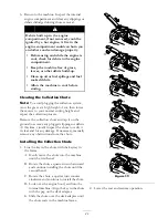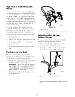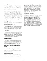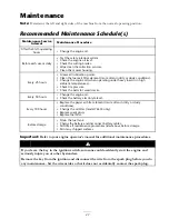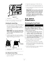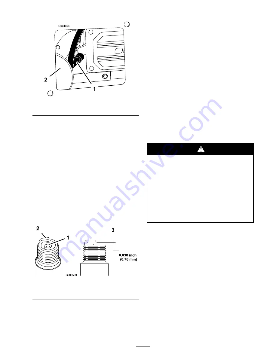
Figure 37
1. Spark plug wire
2. Mufer
4. Remove the spark plug and metal washer.
Checking the Spark Plug
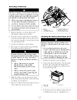
1. Look at the center of the spark plug (Figure 38).
If you see light brown or gray on the insulator,
the engine is operating properly. A black
coating on the insulator usually means the air
cleaner is dirty.
Important:
Never clean the spark plug.
Always replace the spark plug when it has
a black coating, worn electrodes, an oily
film, or cracks.
2. Check the gap between the center and side
electrodes (Figure 38). Bend the side electrode
(Figure 38) if the gap is not correct.
Figure 38
1. Center electrode insulator
3. Air gap (not to scale)
2. Side electrode
Installing the Spark Plug
1. Install the spark plug. Make sure that the air
gap is set correctly.
2. Tighten the spark plug to 30 ft-lb (41 N
⋅
m).
3. Push the wire onto the spark plug (Figure 37).
4. Close the access panel and tighten the fasteners
to secure it shut.
Important:
Always make sure the panel
is replaced and secured with the fasteners
before operating the machine. Operating
the machine with the access panel open
would allow clippings and other debris
entering the engine compartment possibly
damaging the machine.
Fuel System
Maintenance
Draining the Fuel Tank
In certain conditions, fuel is extremely
flammable and highly explosive. A fire or
explosion from fuel can burn you and others
and can damage property.
•
Drain fuel from the fuel tank when the
engine is cold. Do this outdoors in an
open area. Wipe up any fuel that spills.
•
Never smoke when draining fuel, and
stay away from an open flame or where a
spark may ignite the fuel fumes.
1. Park the machine on a level surface and
disengage the blade control switch.
2. Move the motion control levers to the brake
position, stop the engine, remove the key, and
wait for all moving parts to stop before leaving
the operating position.
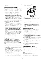
3. Close the fuel shut-off valve located under the
front of the fuel tank (Figure 39).
33
Summary of Contents for TimeCutter ZD420
Page 8: ...Slope Chart 8 ...
Page 49: ...Schematics Electrical Diagram Rev A 49 ...
Page 50: ......
Page 51: ......
Page 52: ......

