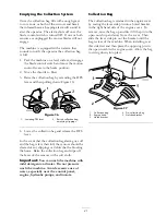
Removing the Battery
Battery terminals or metal tools could short
against metal machine components causing
sparks. Sparks can cause the battery gasses
to explode, resulting in personal injury.
•
When removing or installing the battery,
do not allow the battery terminals to
touch any metal parts of the machine.
•
Do not allow metal tools to short between
the battery terminals and metal parts of
the machine.
1. Park the machine on a level surface and
disengage the blade control switch.
2. Move the motion control levers to the brake
position, stop the engine, remove the key, and
wait for all moving parts to stop before leaving
the operating position.
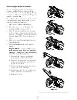
3. Tip the seat forward to see the battery.
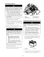
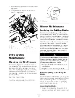
4. Disconnect the negative (black) ground cable
from the battery post (Figure 41).
Incorrect battery cable routing could
damage the machine and cables causing
sparks. Sparks can cause the battery
gasses to explode, resulting in personal
injury.
•
Always disconnect the negative
(black) battery cable before
disconnecting the positive (red)
cable.
•
Always connect the positive (red)
battery cable before connecting the
negative (black) cable.
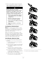
5. Slide the rubber cover up the positive (red)
cable. Disconnect the positive (red) cable from
the battery post (Figure 41).
6. Remove the battery hold-down (Figure 41) and
lift the battery from the battery tray.
Figure 41
1. Battery
4. Negative battery cable
2. Terminal boot
5. Battery hold-down
3. Positive battery cable
6. Bolt, nut, and washer
Checking the Battery Electrolyte Level
Battery electrolyte contains sulfuric acid
which is a deadly poison and causes severe
burns.
•
Do not drink electrolyte and avoid
contact with skin, eyes or clothing. Wear
safety glasses to shield your eyes and
rubber gloves to protect your hands.
•
Fill the battery where clean water is
always available for flushing the skin.
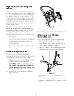
1. Tip the seat forward to see the battery.
2. Look at the side of the battery. The electrolyte
must be up to the Upper line (Figure 42).
Do not allow the electrolyte to fall below the
Lower line (Figure 42).
Figure 42
1. Vent caps
3. Lower line
2. Upper line
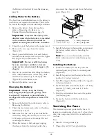
3. If the electrolyte is low, add the required amount
of distilled water; refer to Adding Water to
35
Summary of Contents for TimeCutter ZD420
Page 8: ...Slope Chart 8 ...
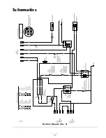
Page 49: ...Schematics Electrical Diagram Rev A 49 ...
Page 50: ......
Page 51: ......
Page 52: ......

