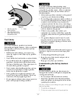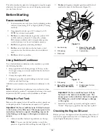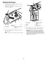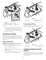
background image

Adjusting the Height of Cut

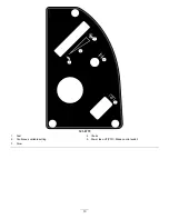
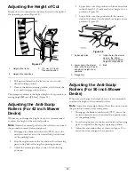
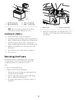
Height-of-cut is controlled by the lever located to the right of
the operating position (Figure 21).

G

015319

1

2

3

Figure 21

1.

Height-of-cut lever

3.

115 mm (4.5 inch),
Transport position

2.

Height-of-cut positions

1.

Pull up and inward on the lever to move it to the
desired cutting position.

2.

Once at the desired cutting position, slowly lower the
lever until it engages the position.

The transport position is the highest height-of-cut position or
cutting height

115

inch [4.5 mm] (Figure 21).

Adjusting the Anti-Scalp
Rollers (For 42 inch Mower
Decks)

Whenever you change the height-of-cut, it is recommended
to adjust the height of the anti-scalp rollers.

Note:

Adjust the anti-scalp rollers so the rollers do not touch

the ground in normal, flat mowing areas.

1.

Disengage the blade control switch (PTO), move the
motion control levers to the neutral lock position and
set the parking brake.

2.

Stop the engine, remove the key, and wait for all moving
parts to stop before leaving the operating position.

3.

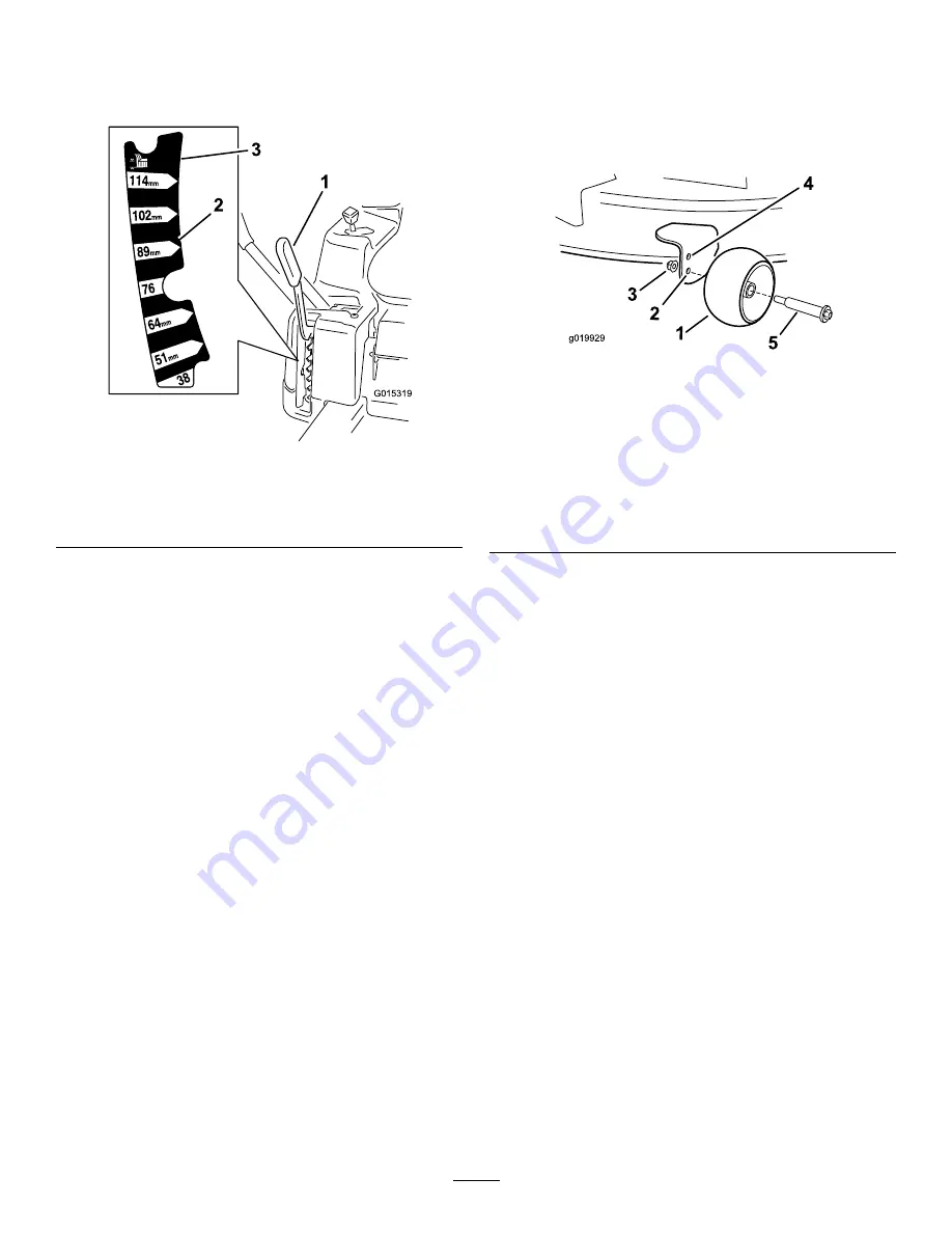
Adjust the anti-scalp rollers to one of the following
positions:

Upper hole—use this position with the mower deck
in the 63mm (2-1/2 inch) and below height-of-cut
positions (Figure 22).

Lower hole—use this position with the mower
deck in the 76mm (3 inch) and above height-of-cut
positions (Figure 22).

g019929

1

2

3

4

5

Figure 22

1.

Anti-scalp roller

4.

Upper hole—the mower
deck in the 63mm
(2-1/2 inch) and below
height-of-cut positions

2.

Lower hole—the mower
deck in the 76mm (3 inch)
and above height-of-cut
positions

5.

Bolt

3.

Flange Nut

Adjusting the Anti-Scalp
Rollers (For 50 inch Mower
Decks)

Whenever you change the height-of-cut, it is recommended
to adjust the height of the anti-scalp rollers.

Note:

Adjust the anti-scalp rollers so the rollers do not touch

the ground in normal, flat mowing areas.

1.

Disengage the blade control switch (PTO), move the
motion control levers to the neutral lock position and
set the parking brake.

2.

Stop the engine, remove the key, and wait for all moving
parts to stop before leaving the operating position.

3.

Adjust the anti-scalp rollers as shown in Figure 23 to
match the closest height-of-cut position.

23

Summary of Contents for TimeCutter ZS 4200

Page 1: ...m No 3375 707 Rev A TimeCutter ZS 4200 or 5000 Riding Mower Model No 74386 Serial No 313000001 and Up Model No 74387 Serial No 313000001 and Up Register at www Toro com Original Instructions EN 3375 707 A ...

Page 2: ...operly and safely You may contact Toro directly at www Toro com for product and accessory information help finding a dealer or to register your product Whenever you need service genuine Toro parts or additional information contact an Authorized Service Dealer or Toro Customer Service and have the model and serial numbers of your product ready Figure 1 identifies the location of the model and seria...

Page 3: ...o Side Discharge For Models with 42 Inch Decks 26 Converting to Side Discharge For Models with 50 Inch Decks 27 Operating Tips 29 Maintenance 30 Recommended Maintenance Schedule s 30 Premaintenance Procedures 31 Raising the Seat 31 Lubrication 31 Greasing the Bearings 31 Engine Maintenance 32 Servicing the Air Cleaner 32 Servicing the Engine Oil 32 Servicing the Spark Plug 34 Cleaning the Cooling ...

Page 4: ...wear and long trousers Do not operate the equipment when barefoot or wearing open sandals Thoroughly inspect the area where the equipment is to be used and remove all objects which may be thrown by the machine Warning Fuel is highly flammable Store fuel in containers specifically designed for this purpose Refuel outdoors only and do not smoke while refuelling Add fuel before starting the engine Ne...

Page 5: ...ety If the fuel tank has to be drained this should be done outdoors When machine is to be parked stored or left unattended lower the cutting means Toro Riding Mower Safety The following list contains safety information specific to Toro products or other safety information that you must know that is not included in the CEN standard Engine exhaust contains carbon monoxide which is an odorless deadly...

Page 6: ...he procedures outlined in EN 836 Whole Body Vibration Measured vibration level 0 33 m s2 Uncertainty Value K 0 16 m s2 Measured values were determined according to the procedures outlined in EN 836 Riding Stand Ons Model 74387 Sound Pressure This unit has a sound pressure level at the operator s ear of 94 dBA which includes an Uncertainty Value K of 1 dBA Sound power level was determined according...

Page 7: ... degrees Use the slope chart to determine the degree of slope of hills before operating Do not operate this machine on a slope greater than 15 degrees Fold along the appropriate line to match the recommended slope 2 Align this edge with a vertical surface a tree building fence pole etc 3 Example of how to compare slope with folded edge 7 ...

Page 8: ...p the deflector in place 2 Cutting dismemberment hazard of hand or foot mower blade stay away from moving parts Manufacturer s Mark 1 Indicates the blade is identified as a part from the original machine manufacturer 99 3943 For Models with 50 Inch Decks 1 Engine 105 7015 For Models with 42 Inch Decks 106 8717 1 Read the instructions before servicing or performing maintenance 2 Check tire pressure...

Page 9: ...emberment of hand or foot stay away from moving parts 112 9840 1 Read the Operator s Manual 3 Remove the ignition key and read the instructions before servicing or performing maintenance 2 Height of cut 114 1606 1 Entanglement hazard belt keep all guards in place 119 8814 1 Parking position 4 Neutral 2 Fast 5 Reverse 3 Slow 119 8815 1 Parking position 4 Neutral 2 Fast 5 Reverse 3 Slow 120 5469 1 H...

Page 10: ...ion hazard 6 Keep bystanders a safe distance from the battery 2 No fire open flame or smoking 7 Wear eye protection explosive gases can cause blindness and other injuries 3 Caustic liquid chemical burn hazard 8 Battery acid can cause blindness or severe burns 4 Wear eye protection 9 Flush eyes immediately with water and get medical help fast 5 Read the Operator s Manual 10 Contains lead do not dis...

Page 11: ...trol on a slope disengage the blade control switch PTO proceed off the slope slowly 3 Cutting dismemberment hazard mower blade entanglement hazard belt stay away from moving parts keep all guards and shields in place 7 Crushing dismemberment hazard of bystanders reversing crushing dismemberment hazard of bystanders do not carry passengers look behind and down when reversing 4 Thrown object hazard ...

Page 12: ...121 0772 1 Fast 4 Choke 2 Continuous variable setting 5 Power take off PTO Blade control switch 3 Slow 12 ...

Page 13: ...121 0773 1 Fast 4 Choke 2 Continuous variable setting 5 Power take off PTO Blade control switch 3 Slow 13 ...

Page 14: ...rol levers 6 Smart Speed lever 9 Control panel 12 Front caster wheel G014910 1 2 3 4 5 6 7 8 9 10 11 12 13 14 15 Figure 5 Models with 50 inch decks 1 Foot assist lever 5 Smart Speed lever 9 Footrest 13 Deflector 2 Height of cut lever 6 Mower deck 10 Gas tank cap 14 Rear drive wheel 3 Motion control levers 7 Anti scalp roller 11 Engine 15 Engine guard 4 Operator seat armrests optional 8 Front caste...

Page 15: ...Take Off The blade control switch represented by a power take off PTO symbol engages and disengages power to the mower blades Figure 6 Motion Control Levers and Park Position The motion control levers are speed sensitive controls of independent wheel motors Moving a lever forward or backward turns the wheel on the same side forward or in reverse wheel speed is proportional to the amount the lever ...

Page 16: ... you your family pets or bystanders avoid injury DANGER Mowing on wet grass or steep slopes can cause sliding and loss of control Wheels dropping over edges can cause rollovers which may result in serious injury death or drowning A loss of traction is a loss of steering control To avoid loss of control and possibility of rollover Do not mow near drop offs or near water Do not mow slopes greater th...

Page 17: ... the ground away from your vehicle before filling Do not fill gasoline containers inside a vehicle or on a truck or trailer bed because interior carpets or plastic truck bed liners may insulate the container and slow the loss of any static charge When practical remove gas powered equipment from the truck or trailer and refuel the equipment with its wheels on the ground If this is not possible then...

Page 18: ...ance of varnish deposits in the fuel system use fuel stabilizer at all times Filling the Fuel Tank Make sure the engine is shut off and the motion controls are in the park position Tank maximum capacity is 2 9 gallons Important Do Not overfill fuel tank Fill the fuel tank to the bottom of the filler neck The empty space in the tank allows the fuel to expand Overfilling may result in fuel leakage o...

Page 19: ...d engine Figure 13 Note A warm or hot engine may not require choking Figure 13 1 Control panel 4 Continuous variable setting 2 Throttle 5 Slow 3 Fast 6 Choke control 4 Turn the ignition key to Start to energize the starter When the engine starts release the key Figure 14 Important Do not engage the starter for more than 10 seconds at a time If the engine fails to start allow a 60 second cool down ...

Page 20: ...ot engage the blades when parked in tall grass Belt or clutch damage can occur 1 Release pressure on the motion control levers and place the machine in neutral 2 Move the throttle to the Fast position Note Always engage the blades with the throttle in the Fast position 3 Pull up on the blade control switch to move it to the On position and engage the blades Figure 15 Figure 15 1 Control panel 2 Bl...

Page 21: ...gure 14 and remove the key Driving Driving the machine benefits from an understanding of what zero turn radius mower means The drive wheels turn independently powered by hydraulic motors on each axle hence one side can turn in reverse while the other turns forward causing the machine to spin rather than turn This vastly improves the machine maneuverability but may require some adjustment if the op...

Page 22: ...ion control levers to neutral Backward 1 Move the levers to the center unlocked position 2 To go backward look behind you and down as you slowly pull the motion control levers rearward Figure 20 G008953 Figure 20 To go straight apply equal pressure to both motion control levers Figure 20 To turn release the pressure on the motion control lever toward the direction you want to turn To stop push the...

Page 23: ...op before leaving the operating position 3 Adjust the anti scalp rollers to one of the following positions Upper hole use this position with the mower deck in the 63mm 2 1 2 inch and below height of cut positions Figure 22 Lower hole use this position with the mower deck in the 76mm 3 inch and above height of cut positions Figure 22 g019929 1 2 3 4 5 Figure 22 1 Anti scalp roller 4 Upper hole the ...

Page 24: ...25 Adjusting the Motion Control Levers Adjusting the Height The motion control levers can be adjusted higher or lower for maximum operator comfort 1 Remove the 2 bolts holding the control lever to the control arm shaft Figure 26 2 Move the control lever to the next set of holes Secure the lever with the 2 bolts Figure 26 4 1 2 G014970 3 Figure 26 1 Control arm shaft 3 Slotted upper hole 2 Control ...

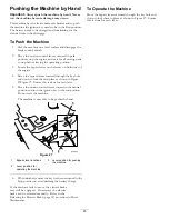
Page 25: ... and down to lock them in place as shown in Figure 23Figure 27 Ensure this is done for each lever 5 Move the motion control levers inward to the neutral position and turn the ignition key to the run position Do not start the machine The machine is now able to be pushed by hand g017303 1 2 3 Figure 27 1 Bypass lever locations 3 Lever position for pushing the machine 2 Lever position for operating t...

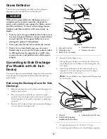
Page 26: ...um mulching and side discharge performance Removing the Discharge Cover for Side Discharge 1 Park the machine on a level surface and disengage the blade control switch 2 Move the motion control levers outward to park position stop the engine remove the key and wait for all moving parts to stop before leaving the operating position 3 Remove the 2 bolts and nuts that secure the discharge cover to th...

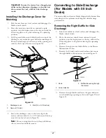
Page 27: ... 1 4 x 2 1 2 inches and two cap nuts 1 4 inch as shown in Figure 30 Note Do not overtighten the nuts this could distort the cover and cause blade contact Converting to Side Discharge For Models with 50 Inch Decks The mower deck and mower blades shipped with this machine were designed for optimum mulching and side discharge performance Removing the Right Baffle for Side Discharge 1 Park the machine...

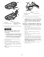
Page 28: ... 5 16 x 3 4 inch 3 Lock nut 5 16 inch 2 Cutoff baffle 10 Torque the fasteners to 14 18 ft lb 7 9 N m 11 Lower the grass deflector over the discharge opening Important Ensure the mower has a hinged grass deflector that disperses clippings to the side and down toward the turf while in side discharge mode Installing the Right Baffle for Mulching 1 Park the machine on a level surface and disengage the...

Page 29: ...t Correct Intervals Normally mow every four days But remember grass grows at different rates at different times So to maintain the same cutting height which is a good practice mow more often in early spring As the grass growth rate slows in mid summer mow less frequently If you cannot mow for an extended period first mow at a high cutting height then mow again two days later at a lower height sett...

Page 30: ...nditions Change the engine oil more often in dusty dirty conditions Check the spark plug s Replace the in line fuel filter Every 200 hours Replace the paper element more often in dusty dirty conditions Change the oil filter more often in dusty dirty conditions Before storage Charge the battery and disconnect battery cables Perform all maintenance procedures listed above before storage Paint any ch...

Page 31: ... 2 Move the motion control levers outward to the park position stop the engine remove the key and wait for all moving parts to stop before leaving the operating position 3 Clean the grease fittings Figure 34 and Figure 35 with a rag Make sure to scrape any paint off of the front of the fitting s 1 G014522 Figure 34 1 Front caster tire Figure 35 Located on the seat pan underside 1 Read the instruct...

Page 32: ...tant Never clean the paper element with pressurized air or liquids such as solvent gas or kerosene Replace the paper element if it is damaged or cannot be cleaned thoroughly Servicing the Engine Oil Oil Type Detergent oil API service SF SG SH SJ or SL Crankcase Capacity Model Oil filter not removed Oil filter removed 74386 1 6 qt 1 5 l 1 8 qt 1 7 l 74387 1 9 qt 1 8 l 2 2 qt 2 1 l Viscosity See the...

Page 33: ...ng the Engine Oil Service Interval After the first 8 hours Change the engine oil Every 100 hours Change the engine oil more often in dusty dirty conditions Note Dispose of the used oil at a recycling center 1 Park the machine so that the drain side is slightly lower than the opposite side to assure the oil drains completely 2 Disengage the PTO move the motion control levers to the neutral locked p...

Page 34: ...il 2 Change the engine oil filter Figure 41 G008748 3 4 1 2 3 4 5 6 Figure 41 Note Ensure the oil filter gasket touches the engine and then an extra 3 4 turn is completed 3 Fill the crankcase with the proper type of new oil refer to Changing the Oil Servicing the Spark Plug Service Interval Every 100 hours Check the spark plug s Make sure the air gap between the center and side electrodes is corre...

Page 35: ...m or cracks If you see light brown or gray on the insulator the engine is operating properly A black coating on the insulator usually means the air cleaner is dirty Set the gap to 0 030 inches 0 76 mm G008794 1 2 Figure 43 Installing the Spark Plug Tighten the spark plug s to 16 ft lb 22 N m 16 ft lb 22 N m G010687 Figure 44 Cleaning the Cooling System Clean the air intake screen from grass and de...

Page 36: ...m the fuel line 1 Park the machine on a level surface and disengage the blade control switch 2 Move the motion control levers outward to the park position stop the engine remove the key and wait for all moving parts to stop before leaving the operating position 3 Locate the fuel filter on the side of the engine as shown in Figure 45 g017471 1 2 3 4 5 Figure 45 1 Fuel line from tank 4 Fuel line to ...

Page 37: ...le from the battery post Figure 46 Retain all fasteners WARNING Incorrect battery cable routing could damage the machine and cables causing sparks Sparks can cause the battery gasses to explode resulting in personal injury Always disconnect the negative black battery cable before disconnecting the positive red cable Always connect the positive red battery cable before connecting the negative black...

Page 38: ...t 5 Secure the battery with the hold down Figure 46 6 Lower the seat Servicing the Fuses The electrical system is protected by fuses It requires no maintenance however if a fuse blows check the component circuit for a malfunction or short Fuse Main F1 30 amp blade type Charge Circuit F2 25 amp blade type 1 Remove the screws securing the control panel to the machine Retain all fasteners 2 Lift the ...

Page 39: ...maximum pressure suggested by the tire manufacturer on the sidewall of the caster wheel tires Inflate the rear drive wheel tires to 12 psi Figure 49 1 Valve stem Releasing the Electric Brake The electric brake can be release by manually rotating the link arms forward Once the electric brake is energized the brake will reset To release the brake G015000 1 Figure 50 1 Brake link arm on the electric ...

Page 40: ...vel surface disengage the blade control switch and move the motion control levers outward to the park position Stop the engine and remove the key Inspecting the Blades Service Interval Before each use or daily Check the cutting blades 1 Inspect the cutting edges Figure 51 If the edges are not sharp or have nicks remove and sharpen the blades refer to Sharpening the Blades 2 Inspect the blades espe...

Page 41: ...amaged blade with a new blade Never file or create sharp notches in the edges or surfaces of blade A If the difference between A and B is greater than 1 8 inch 3mm replace the blade with a new blade Refer to Removing the Blades and Installing the Blades Note If a bent blade is replaced with a new one and the dimension obtained continues to exceed 1 8 inch 3mm the blade spindle could be bent Contac...

Page 42: ...ue the blade bolt to 35 65 ft lb 47 88 N m Leveling the Mower Deck Check to ensure the mower deck is level any time you install the mower or when you see an uneven cut on your lawn The mower deck must be checked for bent blades prior to leveling any bent blades must be removed and replaced Refer to the Checking for Bent Blades procedure before continuing The mower deck must be leveled side to side...

Page 43: ... in the fixed position remove the side carriage bolt and side locking nut from the fixed position and install it into the slotted adjustment position Figure 61 If the bolt is in the slotted position the carriage bolt and side locking nut do not need to be removed G015323 1 2 3 4 5 Figure 61 1 Hanger bracket 4 Side locking nut 2 Slotted adjustment position 5 Side carriage bolt 3 Fixed position 9 Lo...

Page 44: ...d wait for all moving parts to stop before leaving the operating position 3 Set the height of cut lever to middle position Note Check and adjust the side to side blade level if you have not checked the setting refer to Side to Side Leveling 4 Carefully rotate the blades so they are facing front to rear Figure 64 and Figure 65 G009658 1 2 2 Figure 64 Mower Decks with 2 Blades 1 Blades front to rear...

Page 45: ...tion control levers outward to the park position stop the engine remove the key and wait for all moving parts to stop before leaving the operating position 3 Lower the height of cut lever to the lowest position 4 Remove the hairpin cotter from the front support rod and remove the rod from the deck bracket Figure 67 Carefully lower the front of the mower deck to the ground G014635 1 2 3 Figure 67 1...

Page 46: ...ng parts to stop before leaving the operating position 3 Set the height of cut at the lowest cutting position 1 1 2 inch 38 mm 4 Using a spring removal tool Toro part no 92 5771 remove the idler spring from the deck hook to remove tension on the idler pulley and roll the belt off of the pulleys Figure 69 and Figure 70 WARNING The spring is under tension when installed and can cause personal injury...

Page 47: ...in the operator s or bystander s direction and result in serious injury Also contact with the blade could occur Never operate the machine without grass deflector discharge cover or grass collection system in place Inspect the grass deflector for damage before each use Replace any damaged parts before use 1 Locate items shown in Figure 71 G005192 1 2 3 4 5 6 7 Figure 71 1 Mower deck 5 Spring 2 Gras...

Page 48: ...1 Washout fitting 3 O ring 2 Hose 4 Coupling 4 Lower the mower to the lowest height of cut 5 Sit on the seat and start the engine Engage the blade control switch and let the mower run for one to three minutes 6 Disengage the blade control switch stop the engine and remove the ignition key Wait for all moving parts to stop 7 Turn the water off and remove the coupling from the washout fitting Note I...

Page 49: ...s from the stabilizer manufacturer Do not use an alcohol based stabilizer ethanol or methanol Note A fuel stabilizer conditioner is most effective when mixed with fresh gasoline and used at all times Run the engine to distribute the conditioned fuel through the fuel system 5 minutes Stop the engine allow it to cool and drain the fuel tank Restart the engine and run it until it stops Choke the engi...

Page 50: ...spark plug wire s is loose or disconnected 4 Install the wire s on the spark plug 5 The spark plug s is pitted fouled or the gap is incorrect 5 Install a new correctly gapped spark plug s 6 There is dirt in fuel filter 6 Replace the fuel filter 7 Dirt water or stale fuel is in fuel system 7 Contact an Authorized Service Dealer 8 There is incorrect fuel in the fuel tank 8 Drain the tank and replace...

Page 51: ... underside of the mower 6 The tire pressure is incorrect 6 Adjust the tire pressure Uneven cutting height 7 A blade spindle is bent 7 Contact an Authorized Service Dealer 1 The drive belt is worn loose or broken 1 Install a new drive belt 2 The drive belt is off of the pulley 2 Install the drive belt and check the adjusting shafts and belt guides for the correct position 3 The Power Take Off PTO s...

Page 52: ...Schematics G014644 Electrical Diagram Rev A 52 ...

Page 53: ...Notes 53 ...

Page 54: ...Notes 54 ...

Page 55: ...rmation Toro Collects Toro Warranty Company Toro respects your privacy In order to process your warranty claim and contact you in the event of a product recall we ask you to share certain personal information with us either directly or through your local Toro company or dealer The Toro warranty system is hosted on servers located within the United States where privacy law may not provide the same ...

Page 56: ...turer 5Whichever occurs first 6Lifetime Frame Warranty If the main frame consisting of the parts welded together to form the tractor structure that other components such as the engine are secured to cracks or breaks in normal use it will be repaired or replaced at Toro s option under warranty at no cost for parts and labor Frame failure due to misuse or abuse and failure or repair required due to ...

Reviews: