G010233
1
2
3
4
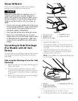
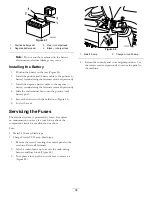
Figure 23
1.
Anti-scalp roller
3.
Flange Nut
2.
Bolt
4.
Hole spacing
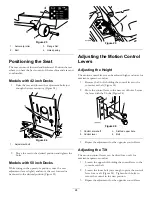
Positioning the Seat
The seat can move forward and backward. Position the seat
where you have the best control of the machine and are most
comfortable.
Models with 42 inch Decks
1.
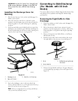
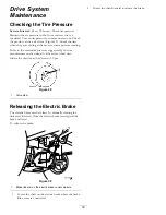
Raise the seat and loosen the adjustment bolts just
enough that seat can move (Figure 24).
G
014477
1
Figure 24
1.
Adjustment bolt
2.
Move the seat to the desired position and tighten the
bolts.
Models with 50 inch Decks
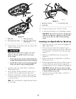
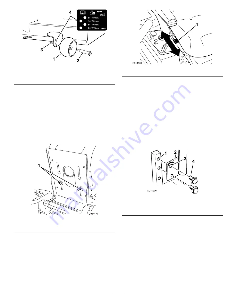
While sitting in the operator’s position, raise the seat
adjustment lever slightly and move the seat forward or
backward to the desired position (Figure 25).
1
G014969
Figure 25
Adjusting the Motion Control
Levers
Adjusting the Height
The motion control levers can be adjusted higher or lower for
maximum operator comfort.
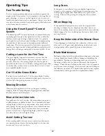
1.
Remove the 2 bolts holding the control lever to the
control arm shaft (Figure 26).
2.
Move the control lever to the next set of holes. Secure
the lever with the 2 bolts (Figure 26).
4
1
2
G014970
3
Figure 26
1.
Control arm shaft
3.
Slotted, upper hole
2.
Control lever
4.
Bolt
3.
Repeat the adjustment for the opposite control lever.
Adjusting the Tilt
The motion control levers can be tilted fore or aft for
maximum operator comfort.
1.
Loosen the upper bolt holding the control lever to the
control arm shaft.
2.
Loosen the lower bolt just enough to pivot the control
lever fore or aft (Figure 26). Tighten both bolts to
secure the control in the new position.
3.
Repeat the adjustment for the opposite control lever.
24
Summary of Contents for TimeCutter ZS 4200
Page 52: ...Schematics G014644 Electrical Diagram Rev A 52 ...
Page 53: ...Notes 53 ...
Page 54: ...Notes 54 ...

