background image

g027590

B

A

C

D

g027518

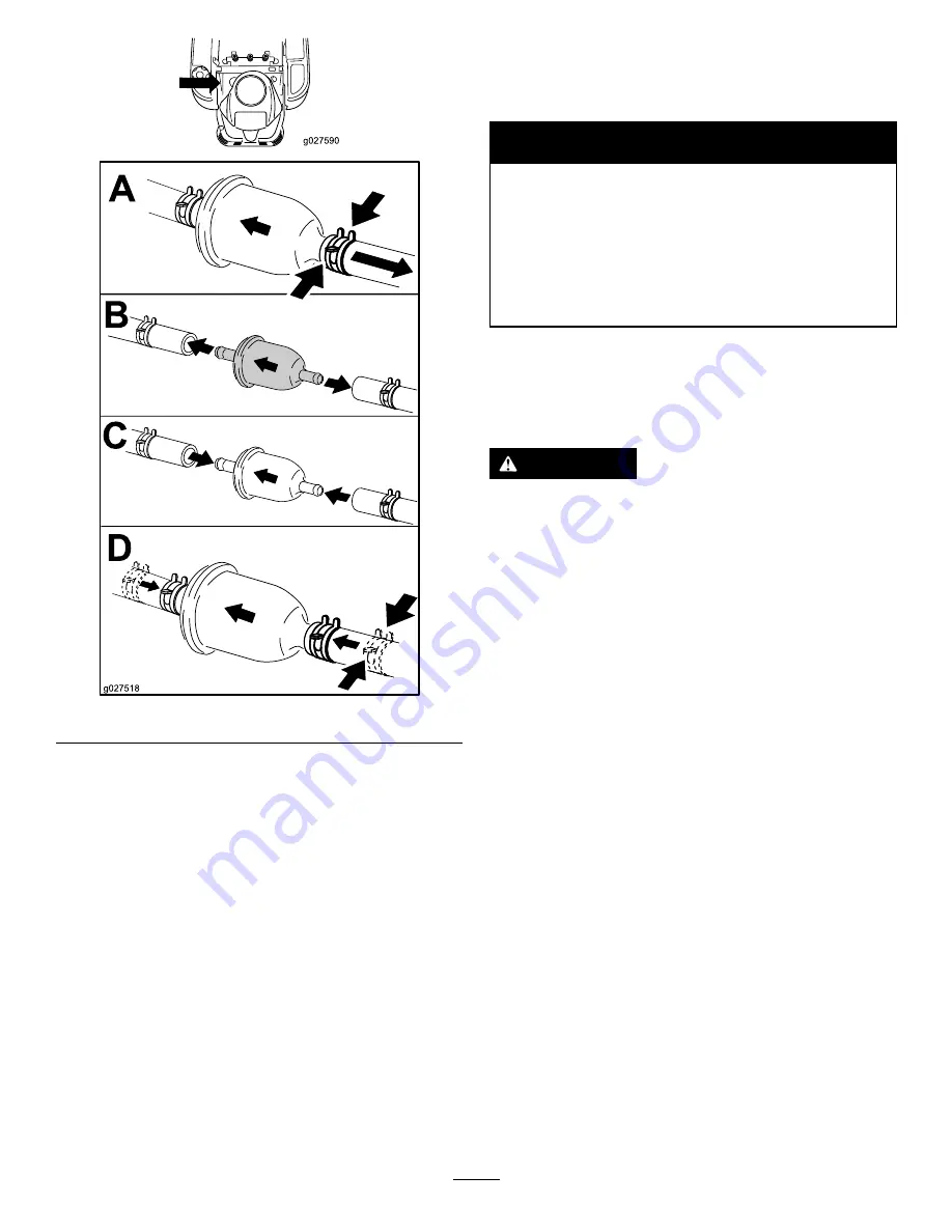
Figure 46

Electrical System
Maintenance

WARNING

CALIFORNIA

Proposition 65 Warning

Battery posts, terminals, and related

accessories contain lead and lead compounds,

chemicals known to the State of California

to cause cancer and reproductive harm.

Wash hands after handling.

Charging the Battery

Removing the Battery

WARNING

Battery terminals or metal tools could short against
metal machine components causing sparks. Sparks
can cause the battery gasses to explode, resulting
in personal injury.

When removing or installing the battery, do not
allow the battery terminals to touch any metal
parts of the machine.

Do not allow metal tools to short between
the battery terminals and metal parts of the
machine.

1.

Park the machine on a level surface and disengage the
blade-control switch.

2.

Move the motion-control levers outward to the park
position, stop the engine, remove the key, and wait for
all moving parts to stop before leaving the operating
position.

3.

Raise the seat to access the battery.

4.

Disconnect the negative (black) ground cable from the
battery post (

Figure 47

).

Note:

Retain all fasteners.

39


Summary of Contents for timecutter zs 4200t

Page 1: ...m No 3394 276 Rev A TimeCutter ZS 4200T or 5000 Riding Mower Model No 74656 Serial No 315000001 and Up Model No 74660 Serial No 315000001 and Up Register at www Toro com Original Instructions EN 3394 276 A ...

Page 2: ...s information carefully to learn how to operate and maintain your product properly and to avoid injury and product damage You are responsible for operating the product properly and safely You may contact Toro directly at www Toro com for product safety and operation training materials accessory information help finding a dealer or to register your product Whenever you need service genuine Toro par...

Page 3: ... inch decks 27 Transporting the Machine 29 Loading the Machine 29 Operating Tips 31 Maintenance 32 Recommended Maintenance Schedule s 32 Premaintenance Procedures 33 Raising the Seat 33 Releasing the Mower Deck Curtain 33 Lubrication 33 Greasing the Bearings 33 Engine Maintenance 34 Servicing the Air Cleaner 34 Servicing the Engine Oil 35 Servicing the Spark Plug 37 Cleaning the Cooling System 38 ...

Page 4: ... clothing including a hard hat safety glasses long pants substantial slip resistant footwear gloves and hearing protection Important Long hair loose clothing or jewelry may get tangled in moving parts Inspect the area where the equipment is to be used and ensure that all objects are removed from the machine before use Use extra care when handling fuels They are flammable and vapors are explosive U...

Page 5: ...om the truck or trailer and fuel it on the ground If this is not possible then add fuel with such equipment as a portable container rather than from a fuel dispenser nozzle Keep the nozzle in contact with the rim of the fuel tank or container opening at all times until fueling is complete Do not use a nozzle lock open device If fuel is spilled on clothing change your clothing immediately Do not ov...

Page 6: ...ss can hide obstacles Use caution near drop offs ditches or embankments Note The machine could suddenly turn over if a wheel goes over the edge of a cliff or ditch or if an edge caves in Use extra care with grass catchers or other attachments Note These can change the stability of the machine Keep all movement on slopes slow and gradual Do not make sudden changes in speed or direction Mow slopes s...

Page 7: ...13 Whole Body Vibration Measured vibration level 0 82 m s2 Uncertainty Value K 0 41 m s2 Measured values were determined according to the procedures outlined in EN ISO 5395 2013 Riding and Stand Ons Model 74660 Sound Pressure This unit has a sound pressure level at the operator s ear of 94 dBA which includes an Uncertainty Value K of 1 dBA Sound power level was determined according to the procedur...

Page 8: ... degrees Use the slope chart to determine the degree of slope of hills before operating Do not operate this machine on a slope greater than 15 degrees Fold along the appropriate line to match the recommended slope 2 Align this edge with a vertical surface a tree building fence pole etc 3 Example of how to compare slope with folded edge 8 ...

Page 9: ...es the blade is identified as a part from the original machine manufacturer 99 3943 For models with 127 cm 50 inch decks 1 Engine 105 7015 For models with 107 cm 42 inch decks 106 8717 1 Read the instructions before servicing or performing maintenance 2 Check tire pressure every 25 operating hours 3 Grease every 25 operating hours 4 Engine 110 6691 1 Thrown object hazard keep bystanders a safe dis...

Page 10: ...erforming maintenance 2 Height of cut 114 1606 1 Entanglement hazard belt keep all guards in place 119 8814 1 Parking position 4 Neutral 2 Fast 5 Reverse 3 Slow 119 8815 1 Parking position 4 Neutral 2 Fast 5 Reverse 3 Slow 120 5469 For models with 107 cm 42 inch decks 1 Height of cut 120 5470 For models with 127 cm 50 inch decks 1 Height of cut 10 ...

Page 11: ...a safe distance from the battery 2 No fire open flame or smoking 7 Wear eye protection explosive gases can cause blindness and other injuries 3 Caustic liquid chemical burn hazard 8 Battery acid can cause blindness or severe burns 4 Wear eye protection 9 Flush eyes immediately with water and get medical help fast 5 Read the Operator s Manual 10 Contains lead do not discard 131 4036 1 Maximum drawb...

Page 12: ...121 0772 1 Fast 4 Choke 2 Continuous variable setting 5 Power take off PTO blade control switch 3 Slow 12 ...

Page 13: ...121 0773 1 Fast 4 Choke 2 Continuous variable setting 5 Power take off PTO blade control switch 3 Slow 13 ...

Page 14: ...and that has an incline less than 15 degrees back up the ramp in reverse and drive forward off the ramp 7 Tipping hazard on slopes do not use on slopes near open water do not use on slopes greater than 15 degrees 2 Warning before servicing engage the parking brake remove the key and the spark plug connection 4 Thrown object hazard keep bystanders away from the machine remove debris from the area b...

Page 15: ...ne guard 3 Motion control levers 6 Smart Speed lever 9 Control panel 12 Front caster wheel Figure 5 Models with 127 cm 50 inch decks 1 Height of cut lever 5 Mower deck 9 Fuel tank cap 13 Rear drive wheel 2 Motion control levers 6 Anti scalp roller 10 Engine 14 Engine guard 3 Operator seat 7 Front caster wheel 11 Control panel 4 Smart Speed lever 8 Footrest 12 Deflector 15 ...

Page 16: ...ntrol Switch Power Take off The blade control switch represented by a power take off PTO symbol engages and disengages power to the mower blades Figure 6 Motion Control Levers and Park Position The motion control levers are speed sensitive controls of independent wheel motors Moving a lever forward or backward turns the wheel on the same side forward or in reverse wheel speed is proportional to th...

Page 17: ...anol or E85 contains up to 85 ethanol Using unapproved gasoline may cause performance problems and or engine damage which may not be covered under warranty Do not use gasoline containing methanol Do not store fuel either in the fuel tank or fuel containers over the winter unless a fuel stabilizer is used Do not add oil to gasoline DANGER In certain conditions gasoline is extremely flammable and hi...

Page 18: ... provide the following benefits Keeps gasoline fresh during storage of 90 days or less For longer storage it is recommended that the fuel tank be drained Cleans the engine while it runs Eliminates gum like varnish buildup in the fuel system which causes hard starting Important Do not use fuel additives containing methanol or ethanol Add the correct amount of gas stabilizer conditioner to the gas N...

Page 19: ...pes When mowing slopes gradually work from lower to higher areas on the incline Avoid sudden turns or rapid speed changes Turn up into an incline when changing directions on slopes Turning down the slope reduces traction Attachments change the handling characteristics of the machine Use extra caution when using attachments with the machine Figure 10 1 Safe zone use the TimeCutter here 3 Water 2 Us...

Page 20: ... the engine the engine should not crank 3 While sitting on the seat move the blade control switch to Off 4 Move either motion control lever to the center unlocked position 5 Try starting the engine the engine should not crank 6 Repeat with the other motion control lever 7 While sitting on the seat move the blade control switch to Off and lock the motion control levers in the park position 8 Start ...

Page 21: ...3 Turn the ignition key to Off and remove the key Driving the Machine Driving the machine benefits from an understanding of what zero turn radius mower means The drive wheels turn independently powered by hydraulic motors on each axle hence one side can turn in reverse while the other turns forward causing the machine to spin rather than turn This vastly improves the machine maneuverability but ma...

Page 22: ...ion control levers to neutral and outward to the park position 2 Disengage the blade control switch 3 Adjust the lever to the desired position The following are only recommendations for use Adjustments will vary by grass type moisture content and the height of the grass Suggested uses Trim Tow Mow Parking X Heavy wet grass X Training X Bagging X Mulching X Normal mowing X Transport X Trim This is ...

Page 23: ...2 To go backward look behind you and down as you slowly pull the motion control levers rearward Figure 18 G008953 Figure 18 To go straight apply equal pressure to both motion control levers Figure 18 To turn release the pressure on the motion control lever toward the direction you want to turn To stop push the motion control levers to neutral Stopping the Machine To stop the machine move the motio...

Page 24: ...tion with the mower deck in the 63 mm 2 1 2 inches and below the height of cut positions Figure 20 Lower hole use this position with the mower deck in the 76 mm 3 inches and above the height of cut positions Figure 20 g019929 1 2 3 4 5 Figure 20 1 Anti scalp roller 4 Upper hole the mower deck in the 63mm 2 1 2 inches and below the height of cut positions 2 Lower hole the mower deck in the 76mm 3 i...

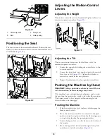
Page 25: ...r fore or aft Figure 23 Tighten both bolts to secure the control in the new position 3 Repeat the adjustment for the opposite control lever Pushing the Machine by Hand Important Always push the machine by hand Do not tow the machine because damage may occur This machine has an electric brake mechanism and to push the machine the ignition key needs to be in the Run position The battery needs to be ...

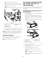
Page 26: ... Discharge for models with 107 cm 42 inch decks The mower deck and mower blades shipped with this machine were designed for optimum mulching and side discharge performance Removing the Discharge Cover for the Side Discharge 1 Park the machine on a level surface and disengage the blade control switch 2 Move the motion control levers outward to park position stop the engine remove the key and wait f...

Page 27: ...rge cover under the grass deflector retaining rod 5 Rotate the discharge cover down over the opening and onto the lower lip of the mower Figure 27 Figure 27 1 Discharge cover 3 Bolt 1 4 x 2 1 2 inches 2 Cap nut 1 4 inch 6 Secure the discharge cover to the lower lip of the mower with 2 bolts 1 4 x 2 1 2 inches and 2 cap nuts 1 4 inch as shown in Figure 27 Note Do not overtighten the nuts this could...

Page 28: ... mower housing Install the hardware in the mounting holes when you remove the mulching baffle 7 Install the right mower blade refer to Removing the Blades page 44 8 Lift up the grass deflector Install 2 bolts 5 16 x 3 4 inch to the two holes along the deck cutout 9 Install the cutoff baffle to the mower deck Figure 30 Note Use the 2 locknuts 5 16 inch to secure the baffle to the mower deck Note Th...

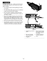
Page 29: ...is dangerous and can lead to accidents causing personal injury Do not drive machine on a public street or roadway To transport the machine 1 If using a trailer connect it to the towing vehicle and connect the safety chains 2 If applicable connect the trailer brakes 3 Load the machine onto the trailer or truck 4 Stop the engine remove the key set the brake and close the fuel valve 5 Tie down the ma...

Page 30: ... as long as the height of the trailer or truck bed to the ground This will ensure that ramp angle does not exceed 15 degrees on flat ground Back up ramps and drive forward down ramps Avoid sudden acceleration or deceleration while driving the machine on a ramp as this could cause a loss of control or a tip over situation g027996 5 1 2 6 Figure 33 1 Full width ramp in stowed position 4 Ramp is at l...

Page 31: ... fertilization Mowing at Correct Intervals Normally mow every 4 days But remember grass grows at different rates at different times So to maintain the same cutting height which is a good practice and mow more often in early spring As the grass growth rate slows in mid summer mow less frequently If you cannot mow for an extended period first mow at a high cutting height then mow again 2 days later ...

Page 32: ... conditions Change the engine oil more often in dusty dirty conditions Check the spark plug s Replace the in line fuel filter Every 200 hours Replace the paper element more often in dusty dirty conditions Change the oil filter more often in dusty dirty conditions Before storage Charge the battery and disconnect battery cables Perform all maintenance procedures listed above before storage Paint any...

Page 33: ...25 hours Grease all the lubrication points Grease Type No 2 general purpose lithium based grease 1 Park the machine on a level surface and disengage the blade control switch 2 Move the motion control levers outward to the park position stop the engine remove the key and wait for all moving parts to stop before leaving the operating position 3 Clean the grease fittings Figure 35 and Figure 36 with ...

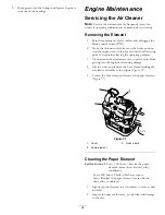
Page 34: ...tion 3 Clean around the air cleaner cover to prevent dirt from getting into the engine and causing damage 4 Lift the cover and remove the hose clamp securing the air cleaner assembly to the engine Figure 37 5 Loosen the hose clamp and remove the paper element Figure 37 G014908 1 2 3 Figure 37 1 Cover 3 Hose clamp 2 Paper element Cleaning the Paper Element Service Interval Every 100 hours Service t...

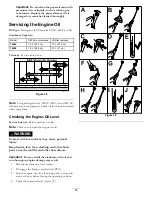
Page 35: ... OIL CHANGE SAE 5W 20 Figure 38 Note Using multi grade oils 5W 20 10W 30 and 10W 40 will increase oil consumption Check oil level more frequently when using them Checking the Engine Oil Level Service Interval Before each use or daily Note Check the oil when the engine is cold WARNING Contact with hot surfaces may cause personal injury Keep hands feet face clothing and other body parts away the muf...

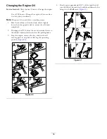
Page 36: ...pposite side to assure the oil drains completely 2 Disengage the PTO move the motion control levers to the neutral locked position and set the parking brake 3 Stop the engine remove the key and wait for all moving parts to stop before leaving the operating position Figure 40 A B C D F E G027539 Figure 40 4 Slowly pour approximately 80 of the specified oil into the filler tube and slowly add the ad...

Page 37: ... side electrodes is correct before installing the spark plug Use a spark plug wrench for removing and installing the spark plug s and a gapping tool feeler gauge to check and adjust the air gap Install a new spark plug s if necessary Type NGK BPR4ES or equivalent Air Gap 0 76 mm 0 03 inch Removing the Spark Plug 1 Disengage the blade control switch PTO 2 Stop the engine wait for all moving parts t...

Page 38: ...n certain conditions gasoline is extremely flammable and highly explosive A fire or explosion from gasoline can burn you others and can damage property Perform any fuel related maintenance when the engine is cold Do this outdoors in an open area Wipe up any gasoline that spills Never smoke when draining gasoline and stay away from an open flame or where a spark may ignite the gasoline fumes Replac...

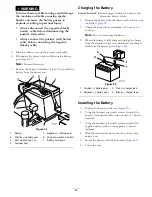
Page 39: ...e battery gasses to explode resulting in personal injury When removing or installing the battery do not allow the battery terminals to touch any metal parts of the machine Do not allow metal tools to short between the battery terminals and metal parts of the machine 1 Park the machine on a level surface and disengage the blade control switch 2 Move the motion control levers outward to the park pos...

Page 40: ... boot Charging the Battery Service Interval Before storage Charge the battery and disconnect battery cables 1 Remove the battery from the chassis refer to Removing the Battery page 39 2 Charge the battery for a minimum of 1 hour at 6 to 10 amps Note Do not overcharge the battery 3 When the battery is fully charged unplug the charger from the electrical outlet then disconnect the charger leads from...

Page 41: ...Maintenance Checking the Tire Pressure Service Interval Every 25 hours Check tire pressure Maintain the air pressure in the front and rear tires as specified Uneven tire pressure can cause uneven cut Check the pressure at the valve stem Figure 50 Check the tires when they are cold to get the most accurate pressure reading Refer to the maximum pressure suggested by the tire manufacturer on the side...

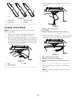
Page 42: ...r damaged blade can break and a piece of the blade could be thrown into the operator s or bystander s area resulting in serious personal injury or death Inspect the blade periodically for wear or damage Replace a worn or damaged blade Before Inspecting or Servicing the Blades Park the machine on a level surface disengage the blade control switch move the motion control levers outward to the park p...

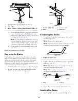
Page 43: ...el surface the machine is on Figure 53 G014972 1 2 3 Figure 53 1 Deck 3 Blade 2 Spindle housing 3 Measure from the tip of the blade to the flat surface Figure 54 G014973 1 2 3 Figure 54 1 Blade in position for measuring 2 Level surface 3 Measured distance between blade and the surface A 4 Rotate the same blade 180 degrees so that the opposing cutting edge is now in the same position Figure 55 G014...

Page 44: ...lacement blades Replacement blades made by other manufacturers may result in non conformance with safety standards 1 Hold the blade end using a rag or thickly padded glove 2 Remove the blade bolt the curved washer and the blade from the spindle shaft Figure 57 G027833 Figure 57 1 Sail area of the blade 3 Curved washer 2 Blade 4 Blade bolt Sharpening the Blades 1 Use a file to sharpen the cutting e...

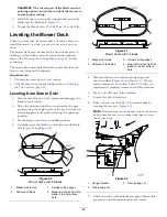
Page 45: ...it for all moving parts to stop before leaving the operating position 3 Set the height of cut lever to middle position 4 Carefully rotate the blade s so that they are all side to side Figure 60 andFigure 61 G009682 1 2 2 3 3 4 4 Figure 60 Mower decks with 2 Blades 1 Blades side to side 3 Outside cutting edges 2 Sail area of blade 4 Measure from the tip of the blade to the flat surface here G005278...

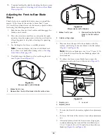
Page 46: ...Figure 63 and Figure 64 G009658 1 2 2 Figure 63 Mower decks with 2 Blades 1 Blades front to rear 2 Measure from the tip of the blade to the flat surface here G009659 1 2 3 2 3 Figure 64 Mower decks with 3 Blades 1 Blades front to rear 3 Measure from the tip of the blade to the flat surface here 2 Outside cutting edges 5 Measure from the tip of the front blade to the flat surface and the tip of the...

Page 47: ...t rod and lower the mower carefully to the ground Figure 67 2 2 3 G005077 1 2 2 3 Figure 67 1 Mower deck 3 Rear lift rod 2 Hanger bracket 8 Slide the mower deck rearward to remove the mower belt from the engine pulley 9 Slide the mower deck out from underneath the machine Note Retain all parts for future installation Installing the Mower 1 Park the machine on a level surface and disengage the blad...

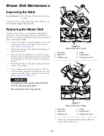
Page 48: ...er Figure 68 G005192 1 2 3 4 5 6 7 Figure 68 1 Mower deck 5 Spring 2 Grass deflector 6 Nut 3 8 inch 3 Grass deflector bracket 7 Short standoff 4 Rod 2 Slide the rod out of the short standoff the spring and the grass deflector Figure 68 3 Remove the damaged or worn grass deflector 4 Replace the grass deflector Figure 68 5 Slide the rod straight end through the rear grass deflector bracket 6 Place t...

Page 49: ... position stop the engine remove the key and wait for all moving parts to stop before leaving the operating position 4 Set the height of cut at the lowest cutting position of 38 mm 1 1 2 inches 5 Using a spring removal tool Toro part no 92 5771 remove the idler spring from the deck hook to remove tension on the idler pulley and roll the belt off of the pulleys Figure 69 and Figure 70 WARNING The s...

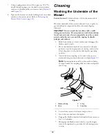
Page 50: ...e control panel under the seat around the engine hydraulic pumps and motors 1 Park the machine on a level surface and disengage the blade control switch 2 Move the motion control levers outward to the park position stop the engine remove the key and wait for all moving parts to stop before leaving the operating position 3 Attach the hose coupling to the end of the mower washout fitting and turn th...

Page 51: ...e the air cleaner refer to Servicing the Air Cleaner page 34 5 Grease and oil the machine refer to Lubrication page 33 6 Change the crankcase oil and filter refer to Servicing the Engine Oil page 35 7 Check the tire pressure refer to Checking the Tire Pressure page 41 8 Charge the battery refer to Charging the Battery page 39 9 Check the condition of the blades refer to Servicing the Cutting Blade...

Page 52: ...underside of the mower then wash the mower with a garden hose 15 Check the condition of the drive and mower belts 16 Check and tighten all bolts nuts and screws Repair or replace any part that is worn or damaged 17 Paint all scratched or bare metal surfaces Paint is available from your Authorized Service Dealer 18 Store the machine in a clean dry garage or storage area Remove the key from the igni...

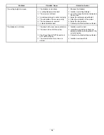
Page 53: ...e spark plug wire s is loose or disconnected 4 Install the wire s on the spark plug 5 The spark plug s is pitted fouled or the gap is incorrect 5 Install a new correctly gapped spark plug s 6 There is dirt in fuel filter 6 Replace the fuel filter 7 Dirt water or stale fuel is in fuel system 7 Contact an Authorized Service Dealer 8 There is incorrect fuel in the fuel tank 8 Drain the tank and repla...

Page 54: ...erside of the mower 6 The tire pressure is incorrect 6 Adjust the tire pressure The cutting height is uneven 7 A blade spindle is bent 7 Contact an Authorized Service Dealer 1 The drive belt is worn loose or broken 1 Install a new drive belt 2 The drive belt is off of the pulley 2 Install the drive belt and check the adjusting shafts and belt guides for the correct position 3 The Power Take Off PT...

Page 55: ...Schematics Electrical Diagram Rev A 55 ...

Page 56: ...Notes 56 ...

Page 57: ...Notes 57 ...

Page 58: ...Notes 58 ...

Page 59: ... 3766 3636 Jean Heybroek b v Netherlands 31 30 639 4611 Victus Emak Poland 48 61 823 8369 European Privacy Notice The Information Toro Collects Toro Warranty Company Toro respects your privacy In order to process your warranty claim and contact you in the event of a product recall we ask you to share certain personal information with us either directly or through your local Toro company or dealer ...

Page 60: ...d or shows signs of being tampered with Owner Responsibilities You must maintain your Toro Product by following the maintenance procedures described in the Operator s Manual Such routine maintenance whether performed by a dealer or by you is at your expense Instructions for Obtaining Warranty Service If you think that your Toro Product contains a defect in materials or workmanship follow this proc...

Reviews: