Electric PTO Clutch- Measuring Clutch Current Draw (continued)
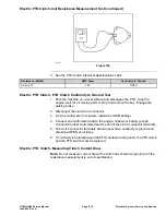
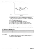
g336411
Figure 127
1. Park the machine on a level surface and disengage the PTO. Stop the
engine, wait for all moving parts to stop, and remove the key. Engage the
parking brake.
2. Disconnect the clutch wire connector.
3.
Set the multi-meter to measure amps (10 amp scale).
4.
Connect the positive meter lead to the chassis harness terminal 1.
5. Connect the negative meter lead to the corresponding wire terminal 2.
6. Connect a short jumper lead from terminal 3 to terminal 4.
7. Turn the ignition switch to RUN and the PTO switch to the ON position.
8. Record the amp reading and refer to the PTO Clutch Electrical Specification
Chart below.
PTO Clutch Electrical Specification Chart
Resistance (OHMs)
AMP Draw
Continuity to Ground
3.05 ± 5%
3.93
OPEN
TVS Diode
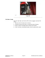
The TVS diode protects the electrical system from current surges caused by
PTO engagement and disengagement.
Electrical System: Service and Repairs
Page 8–16
TITAN® Max Service Manual
3442-428 Rev A
Summary of Contents for TITAN
Page 2: ...Revision History Revision History Page 2 TITAN Max Service Manual 3442 428 Rev A ...
Page 6: ...Preface Page 6 TITAN Max Service Manual 3442 428 Rev A ...
Page 26: ...Troubleshooting General Troubleshooting Page 3 6 TITAN Max Service Manual 3442 428 Rev A ...
Page 36: ...Engine Service and Repairs Page 4 10 TITAN Max Service Manual 3442 428 Rev A ...
Page 70: ...Chassis Service and Repairs Page 5 34 TITAN Max Service Manual 3442 428 Rev A ...
Page 92: ...Mower Deck Service and Repairs Page 6 22 TITAN Max Service Manual 3442 428 Rev A ...
Page 118: ...Electrical System Service and Repairs Page 8 18 TITAN Max Service Manual 3442 428 Rev A ...
Page 121: ... Drawing Rev A Sheet 1 3442 428 Rev A Page A 3 Kohler Engine Electrical Schematic g350654 ...


