background image

Form No. 3442-644 Rev A

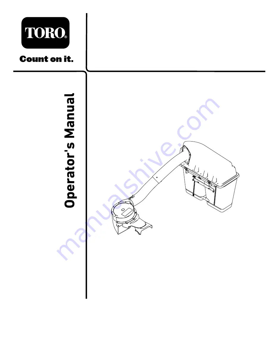
Powered Bagger

TITAN

®

MAX Zero-Turn-Radius Riding Mower

Model No. 79347—Serial No. 400000000 and Up

Register at www.Toro.com.
Original Instructions (EN)

*3442-644*


Summary of Contents for TITAN

Page 1: ...Form No 3442 644 Rev A Powered Bagger TITAN MAX Zero Turn Radius Riding Mower Model No 79347 Serial No 400000000 and Up Register at www Toro com Original Instructions EN 3442 644 ...

Page 2: ...sages that you must follow to avoid accidents This symbol will appear with the word Danger Warning or Caution Danger indicates an imminently hazardous situation which if not avoided will result in death or serious injury Warning indicates a potentially hazardous situation which if not avoided could result in death or serious injury Caution indicates a potentially hazardous situation which if not a...

Page 3: ... while operating near drop offs Keep all movement on slopes slow and gradual Do not make sudden changes in speed direction or turning The grass catcher can obstruct the view to the rear Use extra care when operating in reverse Use care when loading or unloading the machine into a trailer or truck Never operate with the discharge deflector raised removed or altered unless using a grass catcher Keep...

Page 4: ...O remove the key and wait for all moving parts to stop 3 Thrown object hazard do not operate the blower without the entire system installed and latched 6 Warning loss of traction do not operate with only counterbalance weights installed do not operate with only E Z Vac installed operate only with both E Z Vac and counterbalance weights installed decal109 6809 109 6809 1 Crushing hazard of hand do ...

Page 5: ...raction and steering or reduced stability hazard Ez Vac counterbalance weight s installed without the Ez Vac may cause loss of traction and steering control The Ez Vac installed without the Ez Vac counterbalance weight s can cause reduced stability Install weight s only when the Ez Vac is installed decal133 8061 133 8061 5 ...

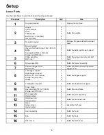
Page 6: ...assembly and belt cover 6 Blower assembly 1 Install the blower assembly Powered bagger cover 1 7 Blower belt 1 Install the blower belt and powered bagger cover Left bagger support 1 Right bagger support 1 Bolt 5 16 x 3 1 4 inches 4 Flange nut 5 16 inch 4 8 Washer 4 Install the bagger support 9 Transmission support 1 Install the transmission support Cross brace 1 Hex head bolt 5 16 x 7 8 inch 4 10 ...

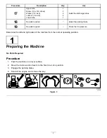
Page 7: ...parking brake 19 No parts required Check the tire pressure Determine the left and right sides of the machine from the normal operating position 1 Preparing the Machine No Parts Required Procedure 1 Park the machine on a level surface 2 Move the motion control levers to the NEUTRAL LOCK position 3 Engage the parking brake 4 Shut off the engine and remove the key g037289 Figure 3 7 ...

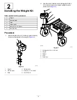
Page 8: ... x 2 1 2 inches nuts 3 8 inch to secure the plates to the weight Figure 4 g185955 Figure 4 1 Weight 4 Tabbed plate 2 Channel plate 5 Bolt 3 8 x 2 1 2 inches 3 Plate 6 Nut 3 8 inch 2 Use the knob washer and carriage bolt 3 8 x 3 1 2 inch to secure a caster weight to each caster arm Figure 5 g037891 Figure 5 1 Carriage bolt 3 8 x 3 1 2 inch 2 Weight 3 Washer 4 Knob 5 Caster arm 8 ...

Page 9: ... to Replacing the Grass Deflector page 29 Inspect the grass deflector for damage before each use Replace any damaged parts before use 1 Disengage the spring from the notch in the deflector bracket and slide the rod out of the welded deck brackets spring and discharge deflector Figure 6 g297555 Figure 6 1 Rod 4 Deck brackets 2 Spring 5 Spring installed over the rod 3 Deflector 2 Remove the deflecto...

Page 10: ...wer support 2 Hex washer head screw 3 8 x 3 4 inch 1 Baffle 4 Carriage bolt 5 16 x 3 4 inch 4 Flange nut 5 16 inch Procedure 1 Install the blower support to the mower deck using 2 hex washer head screws 3 8 x 3 4 inch as shown in Figure 8 g337316 Figure 8 1 Hex washer head screw 3 8 x 3 4 inch 2 Blower support 10 ...

Page 11: ...le aligns with the hole in the mower deck Figure 10 5 Install baffle as shown in Figure 10 6 Tighten the 2 carriage bolts 5 16 x 3 4 inch in the baffle slots Figure 10 g337315 Figure 10 1 Inner baffle 5 Install this carriage bolt 5 16 x 3 4 inch and flange nut 5 16 inch after sliding the baffle 2 Hole for mower deck installation 6 Slots in the baffle 3 Right blade 7 Loosen these 2 carriage bolts 5...

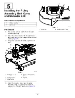
Page 12: ...he right mower deck pulley with the previously removed nut and washer Figure 11 3 Torque the nut to 136 to 149 N m 100 to 110 ft lb g337356 Figure 11 1 Existing pulley nut 4 Existing deck spindle pulley 2 Existing washer 5 Spindle 3 Blower pulley 4 Install the new belt cover over the pulley assembly using the 4 previously removed screws 1 4 x 1 2 inch as shown in Figure 12 g337355 Figure 12 1 Belt...

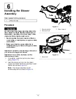
Page 13: ...ass deflector is installed when you remove the grass chute and catcher Important Install the side discharge chute when you remove the bagger and blower Important Save all the hardware and the side discharge chute 1 If necessary install the belt onto the blower pulley Figure 15 2 Insert the blower pivot pin into the blower support and rotate the blower assembly inward toward the machine Figure 13 N...

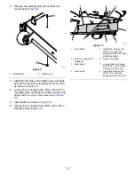
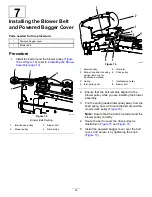
Page 14: ...n housing portion removed for illustrative purposes 6 Drive pulley 3 Spring 7 Idler tension pulley 4 Idler pulley post 8 Blower belt 2 Ensure that the belt remains aligned to the blower pulley while you are installing the blower assembly 3 Pull the spring loaded idler pulley away from the fixed spring post and route the belt around the mower deck pulley Figure 16 Note Ensure that the belt is route...

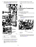
Page 15: ... upper trim to the machine Figure 18 g037892 Figure 18 1 Flange nut 3 Bolt 2 Upper trim 2 Remove and discard the bolts and nuts that secure the left side of the rear guard to the frame Figure 19 g037893 Figure 19 1 Bolt securing the left drive assembly 2 Flange nut securing the left drive assembly 3 Bolt securing the rear guard 4 Flange nut securing the rear guard 3 Remove and set aside the 2 flan...

Page 16: ...tab is installed on the inside of the frame it does not cover the decal 6 Tighten all the hardware that you installed 7 Follow this procedure to install the right support frame 9 Installing the Transmission Support Parts needed for this procedure 1 Transmission support Procedure 1 Remove the 2 flange nuts from the support bolts on the left and right transmissions and set them aside Figure 21 g0378...

Page 17: ...nch and flange nuts to secure the cross brace to the left and right bagger support Figure 22 g276069 Figure 22 1 Hex head bolt 5 16 x 7 8 inch 3 Cross brace 2 Flange nut 5 16 inch 2 Use 2 hex head bolts 5 16 x 7 8 inch and flange nuts to secure the cross brace to the rear guard Figure 23 g276070 Figure 23 1 Flange nut 5 16 inch 3 Cross brace 2 Hex head bolt 5 16 x 7 8 inch 17 ...

Page 18: ... g037900 Figure 24 1 Pivot assembly 2 Hairpin cotter 2 Install the hairpin cotter into the post to secure the pivot assembly to the bagger support Figure 24 12 Installing the Hold Down Rod Parts needed for this procedure 1 Hold down rod 1 Hairpin cotter Procedure 1 Install hold down rod to the pivot assembly Figure 25 g037978 Figure 25 1 Hold down rod 2 Hairpin cotter 2 Use the hairpin cotter to s...

Page 19: ...ood Figure 26 g188636 Figure 26 1 Grass screen 3 Hairpin cotter 2 Hood 14 Installing the Hood Parts needed for this procedure 1 Hood assembly Procedure 1 Align the key hole feature on the pivot bracket to the key on the pivot pin and slide it into position Figure 27 g037979 Figure 27 1 Pivot bracket 2 Pivot pin 2 Rotate the hood to capture it with the pivot pin 19 ...

Page 20: ...gure 28 g037980 Figure 28 1 Bag 2 Pivot assembly 16 Installing the Hitch Cover Parts needed for this procedure 1 Hitch cover Procedure 1 Apply a lubricant to the nipple on the hitch cover 2 Align the hitch cover over the hitch and press it into place Figure 29 g337369 Figure 29 1 Hitch cover 3 Hitch 2 Nipple 20 ...

Page 21: ...0 Note Ensure that the notch in the lower tube is at the bottom when installed Figure 32 g018444 Figure 30 Lower Discharge Tube Latch 1 Blower assembly 3 Latch 2 Upper latch 5 Make note of where the 2 bolts in the upper tube are installed Note The hole near the molded arrowheads will not be used 6 Remove the 2 bolts in the lower end of the upper tube 7 Use the 2 holes as a template for the lower t...

Page 22: ... template drill 2 holes 6 5 mm 1 4 inch diameter through the dimples on the lower tube Figure 33 g018439 Figure 33 Drilling Lower Discharge Tube 1 Dimples 4 Upper tube 2 Lower tube 5 Install screw 1 4 x 3 4 inch washer 1 4 inch and locknut 1 4 inch here 3 Drill 6 5 mm 1 4 inch diameter hole 6 Upper tube existing holes 12 Remove the upper and lower tubes from the machine 13 Slide the tubes together...

Page 23: ... the Parking Brake No Parts Required Procedure Check to ensure that the parking brake is adjusted properly Refer to your Operator s Manual for the correct procedure 19 Checking the Tire Pressure No Parts Required Procedure Increase the tire pressure due to the additional weight Note This is not applicable with semi pneumatic tires Check and increase the air pressure in the front caster wheels and ...

Page 24: ...s or feet under the mower Never try to clear the discharge area or mower blades unless you move the power take off PTO to off and rotate the ignition key to off Also remove the key and pull the wire off of the spark plug s Turn off the engine before unclogging the discharge chute Emptying the Grass Bags DANGER Debris such as leaves grass or brush can catch fire A fire in the engine area can cause ...

Page 25: ... the grass bags and empty them if they are full 4 Remove and separate the discharge tube and chute from the bagger top and mower Using a stick or similar object carefully remove and clear the obstruction from the mower discharge tube chute and the bagger top 5 After you remove the obstruction install the complete bagger system and resume operation Removing the Bagger CAUTION Failing to remove the ...

Page 26: ...peed gets too slow On hills it may be necessary to slow the mower ground speed This helps maintain the engine speed and bagging efficiency Mow downhill whenever possible CAUTION As the bagger fills extra weight is added to the back of the machine If you stop and start suddenly on hills you may lose steering control or the machine may tip Do not start or stop suddenly when going uphill or downhill ...

Page 27: ...can occur from contacting hot surfaces Allow engines especially the muffler to cool before touching WARNING Debris such as leaves grass or brush can catch fire A fire in the engine area can cause personal injury and property damage Keep the engine and muffler area free of debris accumulation Take care when opening the bagger cover to keep debris from falling onto the engine and muffler area Allow ...

Page 28: ... pulley 3 Drive pulley 6 Blower belt 3 Remove the existing bagger belt from the mower deck pulley 4 Remove the blower from the mower deck 5 Remove the existing bagger belt from the blower pulleys 6 Install the new belt around the blower pulleys Figure 36 7 Install the blower onto the blower support 8 Install the new belt around the mower deck pulley Figure 36 9 Pull back on the spring loaded idler...

Page 29: ...welded brackets on the deck as shown in Figure 38 4 Install the spring onto the straight end of the rod 5 Position the spring on the rod as shown in Figure 38 so that the shorter spring end comes from under the rod before the bend and going over the rod as it returns from the bend 6 Lift the loop end of the spring and place it into the notch on the deflector bracket Figure 38 g297573 Figure 38 1 R...

Page 30: ...bagger attachment for damage refer to Inspecting the Bagger page 28 3 Ensure that the grass bags are empty and thoroughly dry 4 Store the bagger in a clean dry place out of direct sunlight This protects the plastic parts and extends the life of the bagger If you must store the bagger outside cover it with a weatherproof cover 30 ...

Page 31: ...er 1 The bags are too full 1 Dump more frequently 2 The engine speed is too low 2 Always operate the engine at full throttle 3 The grass is too wet 3 Cut grass when it is dry 4 The grass is too long 4 Cut no more than 51 to 76 mm 2 to 3 inches or 1 3 of the grass height whichever is less 5 The screen in the bagger hood is plugged 5 Remove debris leaves or grass clippings from the screen 6 The grou...

Page 32: ...Notes ...

Page 33: ...Notes ...

Page 34: ... for marketing purposes Retention of your Personal Information Toro will keep your personal information as long as it is relevant for the above purposes and in accordance with legal requirements For more information about applicable retention periods please contact legal toro com Toro s Commitment to Security Your personal information may be processed in the US or another country which may have le...

Page 35: ...to restaurants grocery stores hotels schools and hospitals and on a wide variety of products Additionally some online and mail order retailers provide Prop 65 warnings on their websites or in catalogs How do the California warnings compare to federal limits Prop 65 standards are often more stringent than federal and international standards There are various substances that require a Prop 65 warnin...

Page 36: ......

Reviews: