g201515
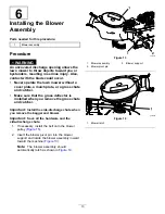
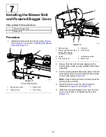
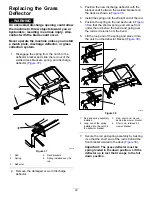
Figure 17
1.
Knob
3.
Belt cover
2.
Powered bagger cover
8
Installing the Bagger
Support (If Applicable)
Parts needed for this procedure:
1
Left bagger support
1
Right bagger support
4
Bolt (5/16 x 3-1/4 inches)
4
Flange nut (5/16 inch)
4
Washer
Procedure
1.
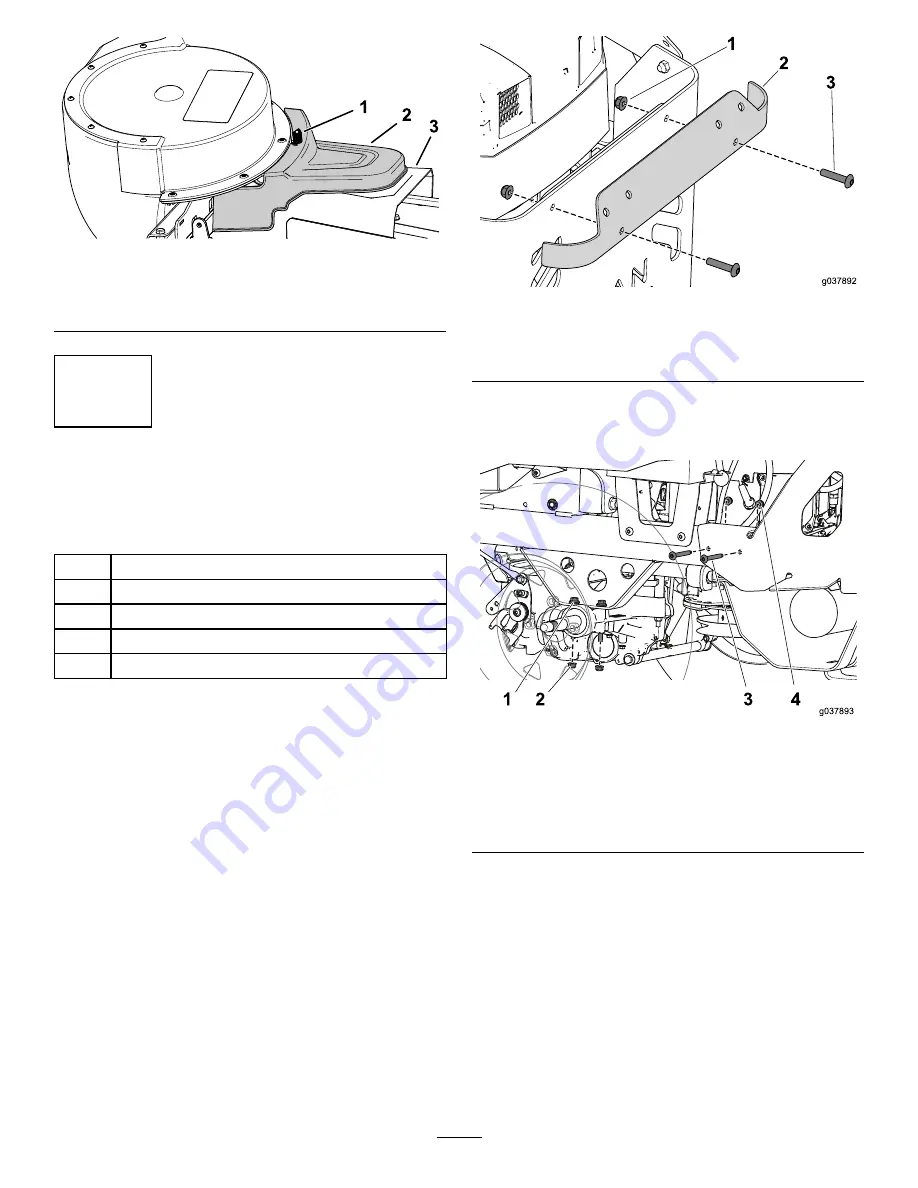
Remove the bolts and nuts that secure the upper
trim to the machine (
).
g037892
Figure 18
1.
Flange nut
3.
Bolt
2.
Upper trim
2.
Remove and discard the bolts and nuts that
secure the left side of the rear guard to the
frame (
).
g037893
Figure 19
1.
Bolt securing the left drive assembly
2.
Flange nut securing the left drive assembly
3.
Bolt securing the rear guard
4.
Flange nut securing the rear guard
3.
Remove and set aside the 2 flange nuts that
secure the left drive assembly to the frame
(
).
Note:
Do not remove the bolts.
15


