4.
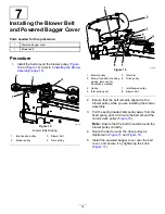
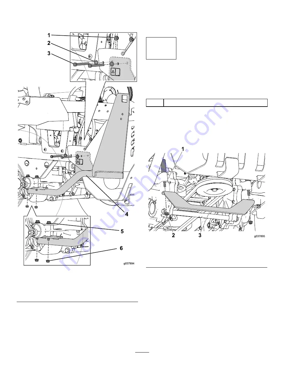
Align the holes on the support to the bolts on the
drive assembly and loosely install the nuts that
you set aside (
g037894
Figure 20
1.
Flange nut (5/16 inch)
4.
Left bagger support
2.
Washer
5.
Drive-assembly bolt
3.
Bolt (5/16 x 3-1/4 inches)
6.
Flange nut (5/16 inch)
5.
Use the 2 bolts (5/16 x 3-1/4 inches) and nuts to
secure the support to the frame (
).
Note:
The support mounting tab is installed on
the inside of the frame; it does not cover the
decal.
6.
Tighten all the hardware that you installed.
7.
Follow this procedure to install the right support
frame.
9
Installing the Transmission
Support
Parts needed for this procedure:
1
Transmission support
Procedure
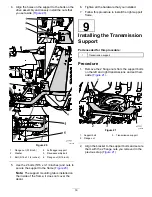
1.
Remove the 2 flange nuts from the support bolts
on the left and right transmissions and set them
aside (
g037895
Figure 21
1.
Support bolt
3.
Transmission support
2.
Flange nut
2.
Align the bracket to the support bolts and secure
them with the 2 flange nuts you removed in the
previous step (
).
16

