26
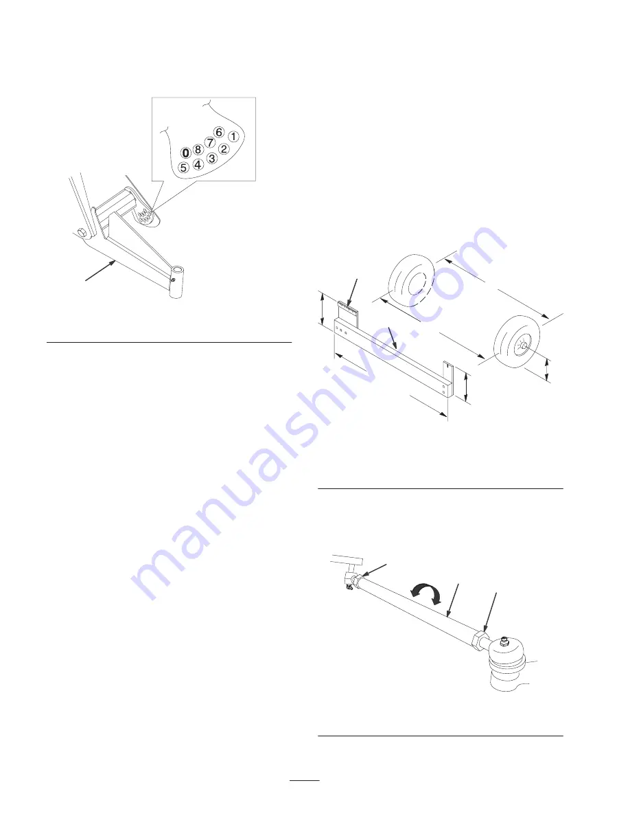
Each hole equals about 3/4 in. (19 mm) of adjustment at the
wheel. You will also need to do this if you are adding heavy
attachments or carrying heavy loads often.
m–5640
1
Figure 25
1.
Left-hand A-arm
6. Torque the ride height adjustment bolt to 135–165 ft.-lb.
(183–224 N
⋅
m).
7. Replace the travel limiting bolt (Fig. 24).
Note: The vehicle may need to be lowered to the ground on
that side to install the bolt.
8. Tighten and torque the centering bolts to
240–290 ft.-lbs. (325–393 N
⋅
m).
9. Check the ride height at the front tongue per the
dimensions and parameters given at the beginning of
this procedure.
Adjusting Front Wheel Toe-In
Check the front wheel toe-in after every 100 operating
hours, or annually, whichever occurs first.
The toe-in should be 1/8–5/8 in. (3–16 mm) with the
following parameters:
•
The tire pressure should be at 12 psi (83 kPa).
•
The ride height should be correct before setting the
toe-in; refer to Adjusting the Front Suspension, page 25.
•
The vehicle should be driven back and forth a few times
to relax the A-arms.
•
Measure the toe-in with the wheels facing straight
ahead and a 175–225 lb. (79–102 kg) operator in the
driver’s seat.
Note: The driver should drive up to the measurement
area and stay seated in the vehicle while the
measurement is being taken.
If the vehicle will be run with medium to heavy loads most
of the time, set the toe-in on the high side of the
recommended amount. If it is going to be run with a light
load most of the time, set the toe-in on the low side of the
recommended amount.
1. Ensure that the front suspension is adjusted properly;
refer to Adjusting the Front Suspension, page 25.
Adjust if necessary.
2. Measure the distance between both of the front tires at
the axle height at both the front and rear of the front
tires (Fig. 26). A fixture or alignment gauge is needed
for the rear measurement of the front tires at axle
height. Use the same fixture or alignment gauge to
accurately measure the front of the front tires at axle
height (Fig. 26).
m–5639
1
2
3
5
5
6
4
52 in.
(132 cm)
Figure 26
1.
Tire center line—back
2.
Tire center line—front
3.
Axle center line
4.
Fixture
5.
Axle center line distance
6.
6 in. (15 cm) ruler
3. If the measurement does not fall within the specified
range (refer to the dimensions and parameters at the
beginning of this procedure),
loosen the jam nuts at
both ends of the tie rods (Fig. 27).
2
1
m–5320
1
Figure 27
1.
Jam nut
2.
Tie rod
Summary of Contents for Twister 12003
Page 8: ...8 ...


