Maintenance
38
1
3
4
5
2
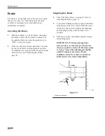
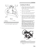
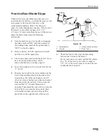
Figure 38
1.
Blade control (PTO) cable
2.
Ring end
3.
Idler spring
4.
Jam nut
5.
Mounting bracket
9.
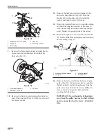
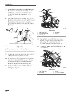
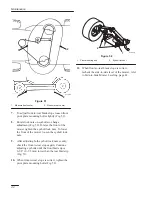
Remove the bolts and lock nuts and pull the two
mower pivot mount brackets down from the
front axle (Fig. 39).
m–4630
1
2
3
Figure 39
1.
Pivot mount bracket
2.
Bolt 5/16–18 x 2-1/2”
3.
Lock nut
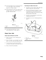
10. Remove the hair pin cotter and washer from the
end of the long rod (Fig. 40). Slide the rod out of
the mower mount.
11. Remove the hair pin cotter and washer at the
mower leveling bracket (Fig. 40). Slide the
bracket off the mounting pin. Re-install the
washer and hairpin cotter for storage.
12. Rotate the leveling bracket up, toward the frame,
and hook the long rod into one of the holes to
store. Secure long rod with washer and hairpin
cotter. Repeat for opposite side of the mower.
13. Move the height-of-cut lever (deck lift) into the
“D” notch. Hook lift assist spring onto retaining
bolt for storage (Fig. 37).
1
3
2
1
4
m–1805
Figure 40
1.
Hair pin cotter and washer
2.
Long rod
3.
Leveling bracket
4.
Mower mount
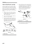
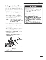
14. Remove the mower belt from the lower engine
pulley (Fig. 41). If you are careful, you can flex
the belt guide(s) just far enough away from the
pulley to remove the belt. If it is too difficult to
remove the belt, loosen the bolts and nuts
securing the belt guides.
IMPORTANT: Do not bend the belt guide(s)
away from the pulley because the belt will not
operate properly when the mower is installed
later.
Summary of Contents for Wheel Horse 16-38 XLE
Page 7: ...Safety 5 Slope Chart Read all safety instructions on pages 2 8...
Page 8: ...6...
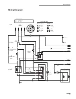
Page 27: ...Maintenance 25 Wiring Diagram...
Page 52: ......

