Assembly
10
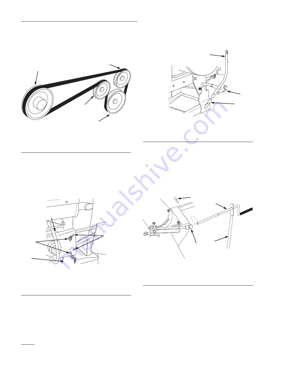
22. Route belt around idler pulleys (Fig. 16).
23. Rotate idler bracket to stretch spring and slip
belt over snowthrower pulley (Fig. 16),
m–2769
1
2
3
2
Figure 16
1.
Outer groove of (PTO)
power take off
2.
Idler pulley
3.
Snowthrower pulley
24. Install belt cover to belt guard bracket and secure
with washers and hairpin cotters (Fig. 17),
Note:
Use inner holes for single cylinder
engines and outer holes for twin
cylinder engines.
m–2591
1
2
3 & 4
5
Figure 17
1.
Belt cover
2.
Belt guard bracket
3.
Washer and hairpin cotter
4.
Single cylinder holes
5.
Twin cylinder holes
25. Slide handle support over pin on frame and
secure with locking clevis pin (Fig. 18).
m–2819
2
1
3
Figure 18
1.
Handle support
2.
Pin
3.
Locking clevis pin
26. Slide crank handle through hole in support and
secure handle to U–Joint with hairpin cotter
(Fig. 19).
Note:
Adjust rotor assembly if necessary so
handle clears tractor hood, teeth mesh
fully and chute turns freely.
1292
2
1
4
3
Figure 19
1.
Crank handle
2.
Support
3.
U-joint
4.
Hairpin cotter


