background image

28

m-1875

1

2

3

4

2

4

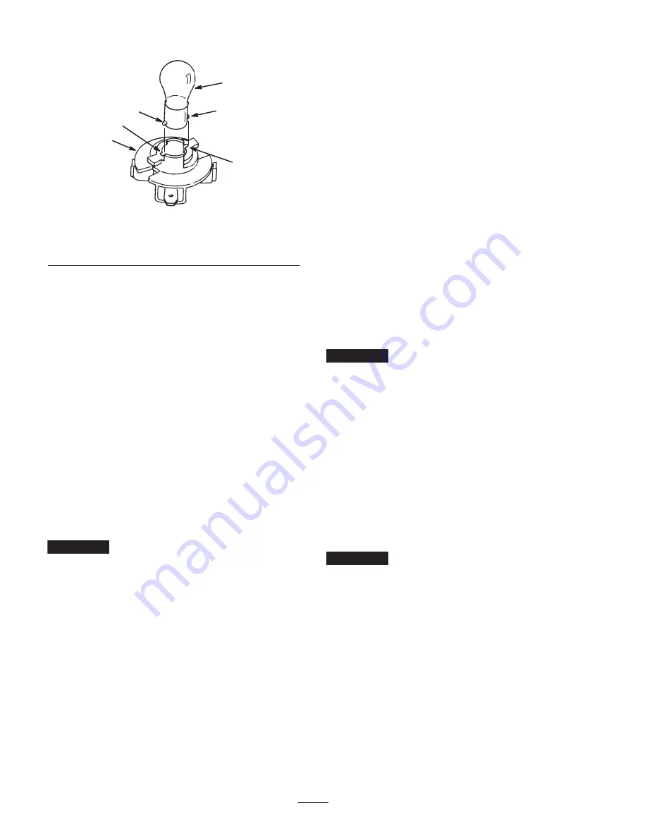
Figure 30

1.

Bulb

2.

Metal pins

3.

Bulb holder

4.

Slots

2. The bulb holder has 2 tabs (Fig. 29). Align the tabs with

the slots in the reflector, insert the bulb holder into the
reflector, and rotate it 1/4 turn clockwise until it stops.

3. Push the wire connectors onto the terminals on the bulb

holder.

Cleaning and Storing the
Tractor

1. Disengage the blades (PTO).

2. Set the parking brake.

3. Stop the engine and wait for all moving parts to stop.

4. Remove the ignition key.

5. Remove grass clippings, dirt, and grime from the

external parts of the entire tractor, especially the engine.
Clean dirt and chaff from the outside of the engine
cylinder head fins and blower housing.

Important


You can wash the tractor with mild

detergent and water. Do not use a pressure washer to
wash the tractor.
 Pressure washing may damage the
electrical system or wash away necessary grease at friction
points. Avoid excessive use of water, especially near the
control panel, lights, engine, and battery.

6. Check the brake; refer to Servicing the Brake on

page 23.

7. Service the air cleaner; refer to Servicing the Air

Cleaner on page 21.

8. Grease the chassis; refer to Greasing and Lubricating

the Tractor on page 23.

9. Change the crankcase oil and filter; refer to Servicing

the Engine Oil on page 20.

10. Check the tire pressure; refer to Checking the Tire

Pressure on page 23.

11. Prepare the tractor for storage when non-use occurs

over 30 days. Prepare tractor for storage as follows.

A. Add a petroleum based stabilizer/conditioner to fuel

in the tank. Follow the mixing instructions from the
stabilizer manufacturer. (1 oz. per gallon). Do not
use an alcohol based stabilizer (ethanol or
methanol).

Note: A fuel stabilizer/conditioner is most effective
when mixed with fresh gasoline and used at all times.

B. Run the engine to distribute conditioned fuel

through the fuel system (5 minutes).

C. Stop the engine, allow it to cool, and drain the fuel

tank; refer to Draining the Fuel Tank on page 26.

D. Restart the engine and run it until it stops.

E. Choke or prime the engine.

F. Start and run the engine until it will not start. Use

the primer, if equipped on the tractor, several times
to ensure that no fuel remains in the primer system.

G. Dispose of fuel properly. Recycle as per local codes.

Important


Do not store stabilizer/conditioned gasoline

over 90 days.

12. Remove the spark plug and check its condition; refer to

Servicing the Spark Plug on page 22. With the spark
plug removed from the engine, pour 2 tablespoons of
engine oil into the spark plug hole. Use the electric
starter to crank the engine and distribute the oil inside
the cylinder. Install the spark plug; refer to Servicing
the Spark Plug on page 22. Do not install the wire on
the spark plug.

13. Disconnect the negative battery cable. Clean the battery

and battery terminals. Check the electrolyte level and
charge it fully; refer to Servicing the Battery on
page 24. Leave the negative battery cable disconnected
from the battery during storage.

Important


The battery must be fully charged to prevent

it from freezing and being damaged at temperatures below
32

°

F (0

°

C). A fully charged battery can be stored during

the winter season without recharging.

14. Check and tighten all bolts, nuts, and screws. Repair or

replace any part that is damaged or defective.

15. Paint all scratched or bare metal surfaces. Paint is

available from an Authorized Service Dealer.

16. Store the tractor in a clean, dry garage or storage area.

Remove the ignition and KeyChoice keys from the
mower and keep them in a memorable place. Cover the
tractor to protect it and keep it clean.

Summary of Contents for Wheel Horse XL 440H

Page 1: ...Operator s Manual Original Instructions EN Register your product at www Toro com Form No 3352 805 Wheel Horse XL 440H Lawn Tractor Model No 71286 Serial No 250000001 and Up ...

Page 2: ...Servicing the Battery 24 Draining the Fuel Tank 26 Replacing the Fuel Filter 26 Servicing the Transaxle Fluid 26 Page Servicing the Fuse 27 Servicing the Headlights 27 Cleaning and Storing the Tractor 28 Wiring Diagram 29 Troubleshooting 30 Introduction Read this manual carefully to learn how to operate and maintain your product properly The information in this manual can help you and others avoid...

Page 3: ...nt wheel grip being driven too fast inadequate braking the type of machine is unsuitable for its task lack of awareness of the effect of ground conditions especially slopes incorrect hitching and load distribution Preparation While mowing always wear substantial footwear and long trousers Do not operate the equipment when barefoot or wearing open sandals Thoroughly inspect the area where the equip...

Page 4: ...connect the spark plug wire s or remove the ignition key before clearing blockages or unclogging chute before checking cleaning or working on the lawnmower after striking a foreign object Inspect the lawnmower for damage and make repairs before restarting and operating the equipment if the machine starts to vibrate abnormally check immediately Disengage drive to attachments when transporting or no...

Page 5: ...und Pressure Level This unit has an equivalent continuous A weighted sound pressure at the operator ear of 87 dB A based on measurements of identical machines per EN 11094 an EN 836 Sound Power Level This unit has a sound power level of 100 Lwa based on measurements of identical machines per EN 11094 Vibration Level This unit has a maximum hand arm vibration level of 10 0 m s2 and whole body vibra...

Page 6: ...6 ...

Page 7: ...7 Slope Chart ...

Page 8: ...8 ...

Page 9: ...to disengage press and release the brake pedal 2 Brake to engage press the brake pedal 3 Traction drive to drive forward press the top of the traction control pedal forward and down to drive in reverse press the bottom of the traction control pedal rearward and down 4 Warning read the Operator s Manual 5 Warning to avoid tipping the tractor do not drive across slopes greater than 5 degrees up slop...

Page 10: ... Engine stop 3 Engine run 4 Engine start 5 Headlights 100 7449 1 Pull the lever out to push the machine 2 Push the lever in to ride on the machine 3 Read the instructions before servicing or performing maintenance 4 Do not tow the machine 104 4163 1 Explosion hazard 2 No fire open flames or smoking 3 Caustic liquid chemical burn hazard 4 Wear eye protection 5 Read the Operator s Manual 6 Keep byst...

Page 11: ...xplosive gases can cause blindness and other injuries 4 No sparks flame or smoking 5 Sulfuric acid can cause blindness or severe burns 6 Flush eyes immediately with water and get medical help fast 7 Maximum fill line 8 Minimum fill line 9 Instructions for activating the battery ...

Page 12: ...r trailer and refuel the equipment with its wheels on the ground If this is not possible refuel such equipment on a truck or trailer from a portable container not from a gasoline dispenser nozzle If you must use a gasoline dispenser keep the nozzle in contact with the rim of the fuel tank or container opening at all times until fueling is complete Using Stabilizer Conditioner Use a fuel stabilizer...

Page 13: ...2 KeyChoice switch Using the Parking Brake Always set the parking brake when you stop the tractor or leave it unattended Setting the Parking Brake 1 Push the clutch brake pedal Fig 3 down and hold it in the depressed position 1 2 Figure 3 1 Clutch brake pedal 2 Parking brake lever 2 Lift the parking brake lever Fig 3 up and gradually take your foot off of the clutch brake pedal The clutch brake pe...

Page 14: ...d 2 On engaged Disengaging the Blades 1 Press the clutch brake pedal to stop the tractor 2 Push the blade control PTO to Disengaged Fig 5 Setting the Height of Cut The height of cut lever is used to raise and lower the mower to the desired cutting height 1 The cutting height may be set in 1 of 7 positions from approximately 1 to 4 in 25 to 102 mm 2 Pull on the height of cut lever and move it to th...

Page 15: ...k System Understanding the Safety Interlock System The safety system is designed to prevent the engine from starting unless The clutch brake pedal is depressed The blade control PTO is in the Disengaged position The safety system is designed to stop the engine if You rise from the seat when the clutch brake pedal is released You rise from the seat when the blade control PTO is in the Engaged posit...

Page 16: ...Disengage the blades PTO to activate the interlock 6 Remove the KeyChoice key and put it in a safe place out of reach of children Testing the Safety Interlock System If safety interlock switches are disconnected or damaged the tractor could operate unexpectedly causing personal injury Do not tamper with the interlock switches Check the operation of the interlock switches daily and replace any dama...

Page 17: ...erate position 2 Push position Note This disengages the drive system and allows the wheels to turn freely Fig 12 To Operate the Machine Push the drive control in to the Operate position Fig 12 Note The machine will not drive unless the drive control is in the Operate position Driving the Tractor Forward or Backward The throttle control regulates the engine speed as measured in RPM revolutions per ...

Page 18: ...omposition and fertilization Grass grows at different rates at different times of the season To maintain the same cutting height which is a good practice mow more often in early spring As the grass growth rate slows in mid summer mow less frequently To improve the quality of cut use a slower ground speed For best operation on average lawns operate the engine at full throttle while controlling the ...

Page 19: ...l of the maintenance procedures listed above Check the belts for wear cracks Drain the fuel tank Paint chipped surfaces Charge the battery and disconnect the cables After storage Check the safety system Check the brakes Check the spark plug Check the battery electrolyte Check the tire pressure 1More often in dusty dirty conditions 2More often when operating the engine under heavy load or in high t...

Page 20: ...wipe the metal end clean Fig 14 9 Screw the oil dipstick fully onto the fill hole Unscrew the dipstick again and look at the metal end If the oil level is low slowly pour only enough oil into the fill hole to raise the level to the Full mark on the dipstick Important Do not overfill the crankcase with oil because the engine may be damaged Changing the Oil 1 Start the engine and let it run for 5 mi...

Page 21: ... yearly whichever occurs first Paper Element Replace after every 100 operating hours or yearly whichever occurs first Note Service the air cleaner more frequently every few hours if operating conditions are extremely dusty or sandy Removing the Foam and Paper Elements 1 Disengage the blades PTO 2 Set the parking brake 3 Stop the engine and wait for all moving parts to stop 4 Remove the ignition ke...

Page 22: ...rk plug wrench for removing and installing the spark plug and a gapping tool feeler gauge to check and adjust the air gap Type Champion QC12YC or equivalent Air Gap 0 030 in 0 76 mm Removing the Spark Plug 1 Disengage the blades PTO 2 Set the parking brake 3 Stop the engine and wait for all moving parts to stop 4 Remove the ignition key 5 Open the hood 6 Disconnect the wire from the spark plug Fig...

Page 23: ...all a new cotter pin and attach the brake arm spring 7 Check the brake operation again refer to Checking the Brake page 23 Important With the parking brake released the rear wheels should rotate freely when you push the tractor If you cannot set the 0 015 in 0 38 mm clearance and get free wheel rotation contact an Authorized Service Dealer immediately Greasing and Lubricating the Tractor Grease th...

Page 24: ... 5 Tip the seat forward to see the battery 6 Disconnect the negative black ground cable from the battery post Fig 23 1 2 3 4 5 m 4965 Figure 23 1 Negative cable black 2 Rubber cover 3 Positive cable red 4 Battery box 5 Bolt and wing nut Incorrect battery cable routing could damage the tractor and cables causing sparks Sparks can cause the battery gasses to explode resulting in personal injury Alwa...

Page 25: ...could be spilled on other parts and cause corrosion 3 Remove the vent caps from the battery Fig 24 4 Slowly pour distilled water into each battery cell until the electrolyte level is up to the Upper line Fig 24 on the battery case Important Do not overfill the battery because electrolyte sulfuric acid can cause severe corrosion and damage to the chassis 5 Wait 5 to 10 minutes after filling the bat...

Page 26: ...all a new fuel filter because the fuel tank is empty 9 Install the fuel line onto the filter Slide the hose clamp close to the filter to secure the fuel line and filter Replacing the Fuel Filter Replace the fuel filter after every 100 operating hours or yearly whichever occurs first The best time to replace the fuel filter Fig 26 is when the fuel tank is empty Never install a dirty filter if it is...

Page 27: ...1156 automotive type bulb Removing the Bulb 1 Disengage the blades PTO 2 Set the parking brake 3 Stop the engine and wait for all moving parts to stop 4 Remove the ignition key 5 Open the hood Pull the wire connectors off of both of the bulb holder terminals 6 Rotate the bulb holder 1 4 turn counterclockwise and remove it from the reflector Fig 29 m 1874 1 2 3 4 4 5 5 Figure 29 1 Bulb holder 2 Ref...

Page 28: ...lizer conditioner is most effective when mixed with fresh gasoline and used at all times B Run the engine to distribute conditioned fuel through the fuel system 5 minutes C Stop the engine allow it to cool and drain the fuel tank refer to Draining the Fuel Tank on page 26 D Restart the engine and run it until it stops E Choke or prime the engine F Start and run the engine until it will not start U...

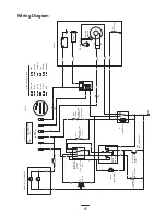
Page 29: ...SEAT SW4 CLUTCH NMIR MODULE 1 3 2 4 6 5 KEY OVER RIDE SW5 SOLENOID B FUEL START AC REG AC BATTERY FUEL SOLENOID MAG STARTER IGNITION MODULE SPARK PLUG Y B S I 2 1 4 X SW3 A WHITE GREY ENGINE 3 IGNITION 5 KEY SW XL SCH VIOLET RED BLUE PTO CLUTCH SHOWN IN NEUTRAL TAN YELLOW WIRE COLOR CODES SWITCH OPENS IN REVERSE SWITCH CLOSES WHEN KEY IS TURNED PTO SWITCH IS SHOWN IN OFF POSITION HEADLIGHT HARNESS...

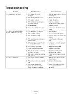
Page 30: ...ith gasoline 3 The air cleaner is dirty 3 Clean or replace the air cleaner element 4 The spark plug wire is loose or disconnected 4 Install the wire on the spark plug 5 The spark plug is pitted fouled or the gap is incorrect 5 Install a new correctly gapped spark plug 6 The choke is not closing 6 Adjust the throttle cable 7 There is dirt in the fuel filter 7 Replace the fuel filter 8 The idle spee...

Page 31: ...ouled or the gap is incorrect 5 Install a new correctly gapped spark plug 6 The vent hole in the fuel cap is plugged 6 Clean or replace the fuel cap 7 There is dirt in the fuel filter 7 Replace the fuel filter 8 Dirt water or stale fuel is in the fuel system 8 Contact an Authorized Service Dealer The tractor does not drive 1 The drive control is in the Push position 2 The traction belt is worn loo...

Page 32: ......

Reviews: