background image

CAUTION: The receiver requires 24 VAC for operation. Connecting the

receiver to a 120/240 VAC power source will result in severe damage. 
The sensor module must not be installed inside a rain gutter or any water
collection vessel. Allowing the sensor to become submerged will result in
severe damage.

Important: 

Installation of this equipment must comply with all applicable

national and local building and electrical codes. Consult local codes prior to
installation.

Install and Connect the Receiver

1. Install the receiver module next to the controller using the stainless steel

screws or double-sided foam tape provided. Position the antenna straight up.

2. Make sure power to the controller has been disconnected.

3. Route the connection cable into the controller cabinet.

Note:

The Wireless RainSensor can operate with either normally-open or

normally-closed sensor circuits. Refer to the controller specifications for 
the sensor type required. If the controller is not equipped for direct sensor
connection, skip step 4 and continue at step 5.

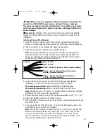
4. Locate the controller’s sensor connection terminals (generally labeled

“SENSOR” or “SEN”) and connect the receiver wires as follows:

For normally-open circuit: 

Attach the WHITE and BROWN wires. 

For normally-closed circuit:

Attach the WHITE and YELLOW wires. 

Note:

Disregard plus (+) and minus ( – ) polarity labels on the sensor terminals

(if present). Cut or tape back the unused wire. 

5. Remove the valve common wire(s) from the terminal labeled “COM”, “C” or “VC.”

6. Attach the BROWN receiver wire to this terminal.

7. Twist the WHITE receiver wire to the valve common wire(s) and secure with the

provided wire nut.

7. Cut or tape back the YELLOW wire.7.

Connect the Red power wires to the

controller’s 24 VAC power source terminals. 

Note: 

The receiver requires a constant source of 24 VAC. The controller may

have two terminals dedicated to 24 VAC input, or a 24 VAC Hot Post and
common terminal. Either connection is acceptable. The receiver will not 
function properly if connected to a 24 VAC source that is switched on and 
off, such as a master valve or pump start circuit.

3

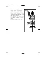
Red – 24 VAC

Red – 24 VAC

White – Sensor Terminal or Valve Common Wire(s)

Brown – Sensor Terminal (Normally-closed)
or Valve Common Terminal

Yellow – Sensor Terminal (Normally-open)
or Valve Common Terminal

Figure 3

Doc 5  12/21/04  6:36 PM  Page 3

Summary of Contents for Wireless RainSensor TWRFS

Page 1: ...ogrammed to delay the controller from resuming operation up to 4 days This feature also enables controller operation to be placed in Rain Delay mode from 1 to 5 days when inclement weather condi tions are expected Now take a moment to browse completely through this guide before starting the installation Since the Wireless RainSensors is an accessory for your irrigation controller it will be helpfu...

Page 2: ...ld 7 Water Conservation LED s Indicate the water conservation level selected 9 Adjust Button Pressed to adjust or select values within the setup and oper ating features 10 Connection Cable Multi wire cable for connection to controller Sensor Module 1 Test Spindle Pressed to manually activate the RainSensor system 2 Rain Threshold Adjustment Adjustable cap enables the rainfall threshold to be set f...

Page 3: ...roller s sensor connection terminals generally labeled SENSOR or SEN and connect the receiver wires as follows For normally open circuit Attach the WHITE and BROWN wires For normally closed circuit Attach the WHITE and YELLOW wires Note Disregard plus and minus polarity labels on the sensor terminals if present Cut or tape back the unused wire 5 Remove the valve common wire s from the terminal lab...

Page 4: ... is visible from the sensor module location Note The manual activation cycle of some controllers bypasses the sensor inputs If the Receiver is connected to the controller s sensor inputs you will need to run an automatic timed watering program for these types of controllers With the sprinklers on manually activate the sensor module by pressing and holding the test spindle The sprinklers should shu...

Page 5: ...er tighten See Figure 7A The sensor module can also be mounted on any suitable solid structure such as the side of the roof a shed or fence using the two supplied stainless steel screws See Figure 7B 2 Once securely fastened adjust the sensor module on the mounting bracket as needed to align the sensor module housing vertically 5 Rain gutter cross section view Do not over tighten thumbscrew Press ...

Page 6: ...splayed 2 Press the Adjust button to select 0 0 to 5 0 Set Temperature Threshold TWRFS models only This feature enables the temperature threshold to be set from 35 F to 45 F or 2 C to 7 C When the selected temperature is observed the sensor will signal to stop irrigation 1 Press the Setup button three times The display will indicate the current temperature threshold setting 2 Press the Adjust butt...

Page 7: ...nded period as set Using the Smart Bypass Feature Your Wireless RainSensor can be temporarily deactivated by using the built in Smart Bypass button Simply press this button once to bypass current RainSensor control The Sensor Status light will blink until the next time the sensor module dries out and automatically resets Pressing the Smart Bypass button again resumes the RainSensor control Pressin...

Page 8: ...ove the battery cover and batteries Replace using two 3V CR2032 or equiva lent batteries Install with positive side of the batteries facing up Note Properly dispose of used batteries per the battery manufacturer s recommen dations 3 Reassemble the unit in reverse order 8 CR2032 Batteries Figure 9 Doc 5 12 21 04 6 36 PM Page 8 ...

Page 9: ... installations with very thick dense walls or that involve large amounts of radio frequency inter ference electrical switching rooms etc where the effective range of the Wireless RainSensor may be greatly reduced Some helpful tips on mounting the sensor module and Receiver for the best Radio Frequency RF performance Always try to keep the antennas straight and fully extended straight up on the Rec...

Page 10: ...stallation However there is no guarantee that interference will not occur in a particular installation If this equipment does cause interference to radio or television reception which can be determined by turning the equipment off and on the user is encouraged to try to correct the interference by one or more of the following measures Reorient the receiving antenna relocate the remote control rece...

Page 11: ...th adjustable rainfall sensitivity Transmitter Battery Type 2 3V cells CR2032 or equivalent Average Battery Life Five years Operating Temperature Range 20 F to 120 F Receiver Power Input 22 28 VACc VDC 100mA from existing controller timer with Class 2 UL approved transformer Relay Contacts Output Normally Open NO and Normally Closed NC 3A at 24 VAC Receiver Controls Sensor Status Indicator Signal ...

Page 12: ...U S call 951 688 9221 This warranty does not apply where equipment is used or installation is performed in any manner contrary to Toro s specifications and instructions nor where equipment is altered or modified Neither Toro nor Toro Warranty Company is liable for indirect incidental or consequential damages in connection with the use of equipment including but not limited to vegetation loss the c...

Reviews: