Greasing the Caster-Wheel
Hubs
Service Interval:
Yearly
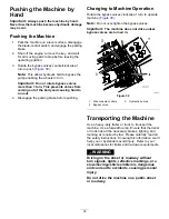
1.
Park the machine on a level surface, disengage
the blade-control switch, and engage the parking
brake.
2.
Shut off the engine, remove the key, and wait
for all moving parts to stop before leaving the
operating position.
3.
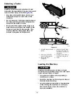
Raise the mower for access.
4.
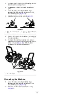
Remove the caster wheel from the caster forks.
5.
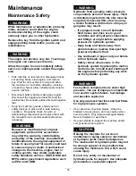
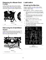
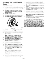
Remove the seal guards from the wheel hub.
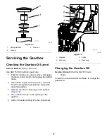
g006115
Figure 54
1.
Seal guard
2.
Spacer nut with wrench
flats
6.
Remove a spacer nut from the axle assembly in
the caster wheel.
Note:
Thread-locking compound has been
applied to lock the spacer nuts to the axle.
7.
Remove the axle (with the other spacer nut still
assembled to it) from the wheel assembly.
8.
Pry out seals and inspect bearings for wear or
damage and replace if necessary.
9.
Pack the bearings with a general-purpose
grease.
10.
Insert 1 bearing and 1 new seal into the wheel.
11.
If the axle assembly is missing both spacer nuts,
apply a thread-locking compound to 1 spacer
nut and thread it onto the axle with the wrench
flats facing outward.
Note:
Do not thread the spacer nut all of
the way onto the end of the axle. Leave
approximately 3 mm (1/8 inch) from the outer
surface of the spacer nut to the end of the axle
inside the nut.
12.
Insert the assembled nut and axle into the wheel
on the side with the new seal and bearing.
13.
With the open end of the wheel facing up, fill
the area inside the wheel around the axle full of
general-purpose grease.
14.
Insert the second bearing and new seal into the
wheel.
15.
Apply a thread-locking compound to the second
spacer nut, and thread it onto the axle with the
wrench flats facing outward.
16.
Torque the nut to 8 to 9 N∙m (75 to 80 in-lb),
loosen the nut, then torque it to 2 to 3 N∙m (20
to 25 in-lb).
Note:
Make sure that the axle does not extend
beyond either nut.
17.
Install the seal guards over the wheel hub, and
insert the wheel into the caster fork.
18.
Install the caster bolt and tighten the nut fully.
Important:
To prevent seal and bearing damage,
check the bearing adjustment often. Spin the
caster tire. The tire should not spin freely (more
than 1 or 2 revolutions) or have any side play. If
the wheel spins freely, adjust the torque on the
spacer nut until there is a slight amount of drag.
Apply another layer of thread-locking compound.
45
Summary of Contents for Z Master Professional 7000 Series
Page 2: ......
Page 84: ...Schematics g012068 Wire Diagram Rev A 82...
Page 86: ......
Page 177: ...Schaltbilder g012068 Schaltbild Rev A 91...
Page 270: ...Sch mas g012068 Sch ma de c blage Rev A 92...
Page 271: ...Remarques...
Page 272: ...Remarques...
Page 274: ......
Page 362: ...Schema s g012068 Elektrisch schema Rev A 88...
Page 364: ......

