Brake Maintenance
Adjusting the Parking
Brake
Service Interval:
Every 25 hours
Every 200 hours
1.
Park the machine on a level surface, disengage
the blade-control switch (PTO), and engage the
parking brake.
2.
Shut off the engine, remove the key, and wait
for all moving parts to stop before leaving the
operating position.
3.
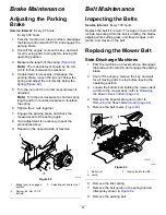
Measure the length of the spring (
).
Note:
The measurement should be 64 mm
(2-1/2 inches) between the washers.
4.
If adjustment is necessary, disengage the
parking brake, loosen the jam nut below the
spring and adjust the nut directly below the
spring (
5.
Turn the nut until the correct measurement is
obtained.
Note:
Turn the nut clockwise to shorten spring
length and turn counter-clockwise to lengthen
the spring.
6.
Tighten the 2 nuts together.
7.
Engage the parking brake and check the
measurement of the spring again.
8.
If an adjustment is necessary, repeat the
procedures above.
9.
Repeat on the opposite side of machine.
g001294
Figure 82
1.
Brake lever in engaged
position
3.
Adjusting nut and jam nut
2.
Spring—64 mm (2-1/2
inches)
Belt Maintenance
Inspecting the Belts
Service Interval:
Every 100 hours
Replace the belt if it is worn. The signs of a worn belt
include squealing while the belt is rotating; the blades
slipping while cutting grass; and frayed edges, burn
marks, and cracks on the belt.
Replacing the Mower Belt
Side-Discharge Machines
1.
Park the machine on a level surface, disengage
the blade-control switch, and engage the parking
brake.
2.
Shut off the engine, remove the key, and wait
for all moving parts to stop before leaving the
operating position.
3.
Loosen the bottom bolt holding the mower-deck
curtain to the mower deck; refer to
the Mower-Deck Curtain (page 42)
.
4.
Remove the sheet-metal guard; refer to
Removing the Sheet-Metal Guard (page 42)
.
5.
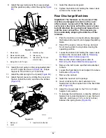
Remove the belt covers (
g006541
Figure 83
1.
Belt cover
3.
Insert slot into the tab
2.
Latch
6.
Remove the idler spring.
7.
Remove the belt guide on the spring-loaded
idler pulley shown in
.
8.
Remove the existing belt.
61
Summary of Contents for Z Master Professional 7000 Series
Page 2: ......
Page 84: ...Schematics g012068 Wire Diagram Rev A 82...
Page 86: ......
Page 177: ...Schaltbilder g012068 Schaltbild Rev A 91...
Page 270: ...Sch mas g012068 Sch ma de c blage Rev A 92...
Page 271: ...Remarques...
Page 272: ...Remarques...
Page 274: ......
Page 362: ...Schema s g012068 Elektrisch schema Rev A 88...
Page 364: ......

