6.
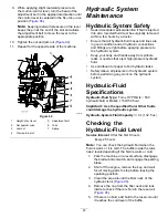
Run the machine at low idle for 15 minutes to
allow any air to purge out of the system and
warm the fluid; refer to
Normal Weather (page 26)
.
Note:
Check the fluid level while the fluid is
warm. The fluid should be between cold and hot.
7.
If required, add fluid to the hydraulic tank.
Note:
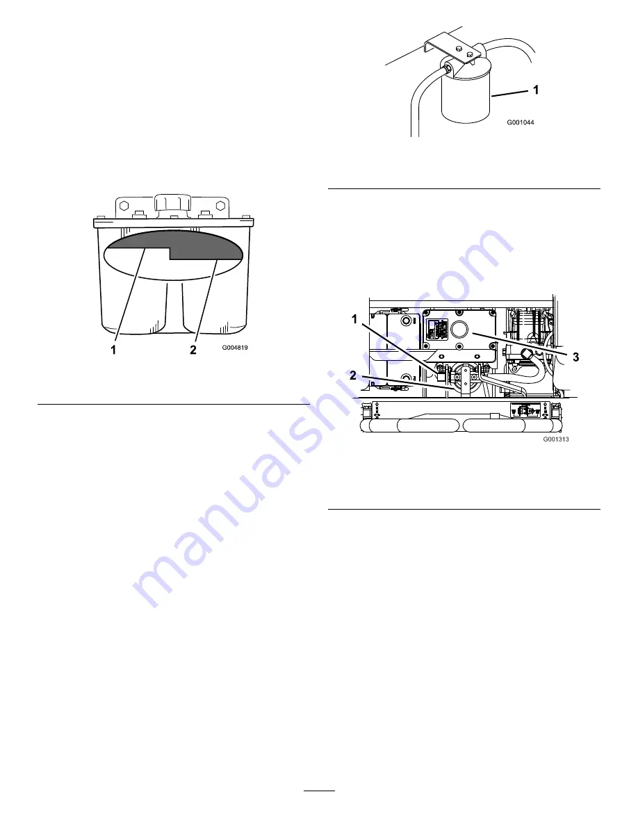
The fluid level should be to the top of
the hot level of the baffle, when the fluid is hot
(
).
8.
Install the cap on the filler neck.
g004819
Figure 95
1.
Hot fluid level—full
2.
Cold fluid level—full
Changing the Hydraulic
Fluid and Filter
Service Interval:
After the first 25 hours
Every 250 hours—Change the hydraulic filter
and hydraulic fluid when using Mobil
®
1 fluid.
Every 500 hours—Change the hydraulic
filter and hydraulic fluid when using Toro
®
HYPR-OIL
™
500 hydraulic fluid.
Use summer filter above 0°C (32°F)
Use winter filter below 0°C (32°F)
1.
Park the machine on a level surface, disengage
the blade-control switch, and engage the parking
brake.
2.
Shut off the engine, remove the key, and wait
for all moving parts to stop before leaving the
operating position.
Important:
Do not substitute automotive
oil filter or severe hydraulic system damage
may result.
3.
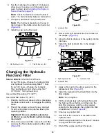
Place drain pan under filter, remove the old filter
and wipe the filter adapter gasket surface clean
(
).
g001044
Figure 96
1.
Hydraulic filter
4.
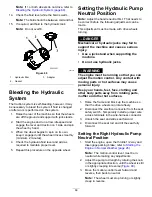
Remove the right hydraulic line that comes into
the adapter (
5.
Allow the fluid to drain out of the system into the
drain pan.
6.
Install the right hydraulic line to the adapter
(
).
g001313
Figure 97
1.
Right hydraulic line
3.
Hydraulic tank
2.
Hydraulic filter
7.
Apply a thin coat to the rubber gasket on the
replacement filter (
).
8.
Install the replacement hydraulic filter onto the
filter adapter.
Note:
Do not tighten.
9.
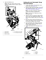
Fill the hydraulic tank with hydraulic fluid until
the fluid overflows the filter and then turn the
fluid filter clockwise until the rubber gasket
contacts the filter adapter, then tighten the filter
an additional 1/2 turn (
10.
Clean up any spilled fluid.
11.
Add fluid to the cold level of the baffle in the
hydraulic tank.
12.
Start the engine and let it run for about 2 minutes
to purge air from the system.
13.
Shut off the engine and check for leaks.
68
Summary of Contents for Z Master Professional 7000 Series
Page 2: ......
Page 84: ...Schematics g012068 Wire Diagram Rev A 82...
Page 86: ......
Page 177: ...Schaltbilder g012068 Schaltbild Rev A 91...
Page 270: ...Sch mas g012068 Sch ma de c blage Rev A 92...
Page 271: ...Remarques...
Page 272: ...Remarques...
Page 274: ......
Page 362: ...Schema s g012068 Elektrisch schema Rev A 88...
Page 364: ......

