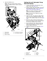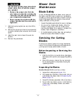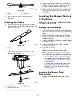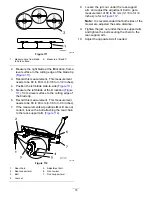
Adjusting the Front-to-Rear Mower
Deck Pitch
1.
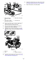
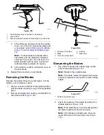
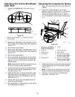
Position the
right
blade front-to-rear (
g001041
Figure 113
1.
Measure here from blade
to hard surface
2.
Measure at A and B
2.
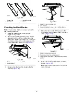
Measure the right blade at the
A
location, from a
level surface to the cutting edge of the blade tip
(
).
3.
Record this measurement.
4.
Measure the right blade at the
B
location, from a
level surface to the cutting edge of the blade tip
(
).
5.
Record this measurement.
6.
The mower blade should be 6 to 10 mm (1/4 to
3/8 inch) lower at position
A
than at position
B
(
). If it is not correct, proceed to the
following steps.
Note:
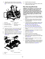
Adjust both of the front swivels the same
amount to maintain equal chain tension.
7.
Loosen the front swivel jam nuts, at the front of
the right and left swivels, approximately 13 mm
(1/2 inch) (
).
8.
Adjust the lift nuts on both the left and the right
side of the machine to achieve 6 to 10 mm (1/4
to 3/8 inch) lower in front at
A
than in the rear
at
B
(
9.
Tighten both swivel jam nuts against the front
swivel to lock the height.
10.
Ensure that there is equal tension on the chains
and adjust again if needed.
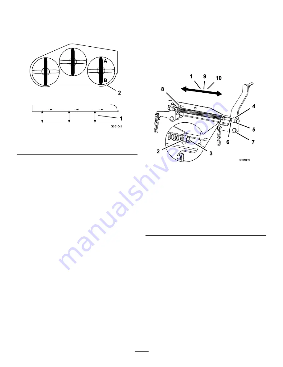
Adjusting the Compression Spring
1.
Raise the mower deck lift lever to the transport
position.
2.
Check the distance between the 2 large
washers, it needs to be 28.2 cm (11-1/8 inches)
for 52-inch mower decks, 26.7 cm (10-1/2
inches) for 60-inch mower decks, or 29.2 cm
(11-1/2 inches) for 72-inch mower decks (
g002479
Figure 114
1.
28.2 cm (11-1/8 inches)
between the large washers
for 52-inch mower decks
6.
Lift nut
2.
Front nut
7.
Front-support arm
3.
Spring-jam nut
8.
Large washer
4.
Front swivel
9.
26.7 cm (10-1/2 inches)
between the large washers
for 60-inch mower decks
5.
Swivel jam nut
10.
29.2 cm (11-1/2 inches)
between the large washers
for 72-inch mower decks
3.
Adjust this distance, by loosening the spring-jam
nut and turning the nut in front of each spring
(
).
Note:
Turning the nut clockwise shortens the
spring; counter-clockwise lengthens the spring.
4.
Lock the nut into position by tightening the
spring-jam nut (
).
76
Summary of Contents for Z Master Professional 7000 Series
Page 2: ......
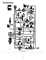
Page 84: ...Schematics g012068 Wire Diagram Rev A 82...
Page 86: ......
Page 177: ...Schaltbilder g012068 Schaltbild Rev A 91...
Page 270: ...Sch mas g012068 Sch ma de c blage Rev A 92...
Page 271: ...Remarques...
Page 272: ...Remarques...
Page 274: ......
Page 362: ...Schema s g012068 Elektrisch schema Rev A 88...
Page 364: ......

