background image

42

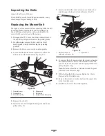
4. Tighten the locknut until the spring washers are flat,

then back off 1/4 turn to properly set the pre-load on the
bearings (Fig. 47).

Important


Ensure that the spring washers are installed

correctly as shown in Figure 47.

Checking the Wheel Hub
Slotted Nut

Check after every 500 operating hours.

The slotted nut needs to be torqued to 125 ft-lb (170 N

m).

1. Disengage the PTO, move the motion control levers to

the neutral locked position, and set the parking brake.

2. Stop the engine, remove the key, and wait for all

moving parts to stop before leaving the operating
position.

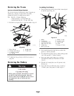
3. Remove the cotter pin.

4. Torque the slotted nut to 125 ft-lb (170 N

m) (Fig. 48).

3

m–4638

1

2

4

5

Figure 48

1.

Slotted nut

2.

Two threads or less
showing

3.

Hole in threaded shaft

4.

Washer (if needed)

5.

Slot

5. Check the distance from the bottom of the slot in the

nut to the inside edge of the hole.

Note: No more than 2 threads should be showing
(Fig. 48).

6. If more than 2 threads are showing, remove the nut and

install a washer between the hub and nut (Fig. 48).

7. Torque the slotted nut to 125 ft-lb (170 N

m) (Fig. 48).

8. Tighten the nut until the next set of slots line up with

the hole in the shaft (Fig. 48).

9. Install the cotter pin.

Leveling the Mower at Three
Positions

Important


There are only 3 measuring positions

needed to level the mower.

Setting Up the Machine

1. Position mower on a flat surface.

2. Disengage the PTO, move the motion control levers to

the neutral locked position, and set the parking brake.

3. Stop the engine, remove the key, and wait for all

moving parts to stop before leaving the operating
position.

4. Check tire pressure of all 4 tires. If needed, adjust them

to 13 psi (90 kPa)

5. Position the mower to the 3-inch (76 mm) height-of-cut

position.

6. Inspect the 4 chains; the chains need to have tension.

Note: Adjust the rear chains to the top of the slot, where
they are attached to the mower.

If one rear chain is loose, lower (loosen) the front
support arm on the same side. Refer to Adjusting the
Front-to-Rear Mower Pitch on page 43.

If one front chain is loose, raise (tighten) the front
support arm for that chain. Refer to Adjusting the
Front-to-Rear Mower Pitch on page 43.

Leveling the Mower Side-to-Side

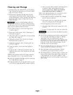
1. Position the right blade front to rear (Fig. 49).

Front

B

m–1078

C

Figure 49

Summary of Contents for Z Master TURBO FORCE Z453

Page 1: ...Operator s Manual Original Instructions GB Register your product at www Toro com Form No 3351 718 Z453 Z Master With 132cm TURBO FORCE Side Discharge Mower Model No 74416TE Serial No 250000001 and Up...

Page 2: ...26 Maintenance 27 Recommended Maintenance Schedule 27 Servicing the Cutting Blades 28 Cleaning the Cooling System 30 Servicing the Air Cleaner 31 Page Servicing the Engine Oil 32 Servicing the Spark...

Page 3: ...wner can result in injury To reduce the potential for injury comply with these safety instructions and always pay attention to the safety alert symbol which means CAUTION WARNING or DANGER personal sa...

Page 4: ...turning do not stop or start suddenly when on a slope use slow speeds on slopes and during tight turns stay alert for humps and hollows and other hidden hazards Use care when pulling loads or using he...

Page 5: ...es and clothing Protect your face eyes and clothing when working with a battery Battery gases can explode Keep cigarettes sparks and flames away from battery Use only genuine Toro replacement parts to...

Page 6: ...a guaranteed sound power level of 100 dBA based on measurements of identical machines per Directive 2000 14 EC Vibration This machine does not exceed a hand arm vibration level of 3 9 m s2 based on me...

Page 7: ...7 Slope Chart Fold along appropriate line Align this edge with a vertical surface Tree Building Fence post pole etc Example Compare slope with folded edge...

Page 8: ...8...

Page 9: ...parts 93 7818 1 Warning read the Operator s Manual for instructions on torquing the blade bolt nut to 115 149 N m 85 110 ft lb 93 7824 1 Thrown object hazard stay a safe distance from the machine 2 T...

Page 10: ...e 99 8944 1 Explosion hazard wear eye protection 2 Caustic liquid chemical burn hazard to perform first aid flush with water 3 Fire hazard no fire open flames or smoking 4 Poison hazard keep children...

Page 11: ...nance necessary 107 1866 1 Sliding and loss of control hazard and tipping hazard dropoffs do not operate the machine near dropoffs slopes greater than 15 degrees or water keep a safe distance from dro...

Page 12: ...7 3069 1 Warning there is no rollover protection when the roll bar is down 2 To avoid injury or death from a rollover accident keep the roll bar in the raised and locked position and wear the seat bel...

Page 13: ...arse grass and dry conditions 2 Bagging 3 Long thick grass and wet conditions 107 9309 1 Warning read the Operator s Manual for information on charging the battery contains lead do not discard 2 Read...

Page 14: ...trained before operating the machine wear hearing protection 5 Return levers to the neutral locked position engage the parking brake and remove the ignition key before leaving the machine 6 Thrown obj...

Page 15: ...losion hazard 2 No fire open flames or smoking 3 Caustic liquid chemical burn hazard 4 Wear eye protection 5 Read the Operator s Manual 6 Keep bystanders a safe distance from the battery 7 Wear eye pr...

Page 16: ...er from a portable container rather than from a gasoline dispenser nozzle If you must use a gasoline dispenser nozzle keep the nozzle in contact with the rim of the fuel tank or container opening at a...

Page 17: ...wn position Drive slowly and carefully Raise the roll bar as soon as clearance permits Check carefully for overhead clearances e g branches doorways and electrical wires before driving under any objec...

Page 18: ...eath or drowning There is no rollover protection when the roll bar is down Always keep the roll bar in the raised and locked position and use the seat belt Read and follow the rollover protection inst...

Page 19: ...1 Hour meter Using the Fuel Shutoff Valve The machine has 2 fuel tanks one on the left side and the other on the right side Each tank connects to a check valve and then to a tee From there a common f...

Page 20: ...arter When the engine starts release the key Fig 14 Important Do not engage the starter for more than 10 seconds at a time If the engine fails to start allow a 30 second cool down period between attem...

Page 21: ...The power takeoff PTO is disengaged The motion control levers are in the neutral lock position The safety interlock system is also designed to stop the engine when you move the traction controls with...

Page 22: ...engine will stop if you move the traction control levers while the parking brake is engaged Driving Backward 1 Move the levers to the center unlocked position 2 To go backward slowly pull the motion...

Page 23: ...nti scalp rollers Adjusting the Outer Rollers 1 Disengage the PTO move the motion control levers to the neutral locked position and set the parking brake 2 Stop the engine remove the key and wait for...

Page 24: ...1 m 3655 Figure 20 1 Adjustment lever 2 Slide the seat to the desired position and release the lever to lock the seat in position Pushing the Machine by Hand Important Always push the machine by hand...

Page 25: ...heels Securely fasten the machine to the trailer or truck with straps chains cable or ropes Secure a trailer to the towing vehicle with safety chains Driving on a street or roadway without turn signal...

Page 26: ...blade Cutting more than that is not recommended unless grass is sparse or it is late fall when grass grows more slowly Mowing Direction Alternate the mowing direction to keep the grass standing straig...

Page 27: ...1 Grease the mower support and push arms Grease the blade spindle bearings Grease both idler pulley pivots Grease the front wheels Check the tire pressure Check the belts for wear and cracks Every 100...

Page 28: ...replace it immediately with a genuine Toro replacement blade For convenient sharpening and replacement keep extra blades on hand Danger A worn or damaged blade can break and a piece of the blade coul...

Page 29: ...ed could break apart and could seriously injure or kill you or bystanders Always replace a bent or damaged blade with a new blade Never file or create sharp notches in the edges or surfaces of a blade...

Page 30: ...Balancer Installing the Blades 1 Install the blade onto the spindle shaft Fig 26 Important The curved part of the blade must be pointing upward toward the inside of the mower to ensure proper cutting...

Page 31: ...ter is damaged Replace both filters 7 Inspect the primary filter for damage by looking into the filter while shining a bright light on the outside of the filter Holes in the filter will appear as brig...

Page 32: ...to the filler hole and damage the engine m 7449 2 1 Figure 31 1 Oil dipstick 2 Filler tube 5 Unscrew the oil dipstick and wipe the end clean Fig 31 6 Slide the oil dipstick fully into the filler tube...

Page 33: ...rubber gasket contacts the filter adapter then tighten the filter an additional 3 4 turn Fig 33 5 Fill the crankcase with the proper type of new oil refer to Servicing the Engine Oil on page 32 6 Run...

Page 34: ...ait for all moving parts to stop before leaving the operating position 3 Allow the machine to cool down 4 Stop the engine remove the key and wait for all moving parts to stop before leaving the operat...

Page 35: ...e any paint off the front of the fitting s 4 Connect a grease gun to the fitting and pump grease into the fittings until the grease begins to ooze out from the bearings 5 Wipe up any excess grease Whe...

Page 36: ...ly whichever occurs first Fig 39 Check the tires when they are cold to get the most accurate pressure reading Pressure 13 psi 90 kPa drive wheels and caster wheels 1 m 1872 Figure 39 1 Valve stem Serv...

Page 37: ...n a few hours by a doctor familiar with this type of injury otherwise gangrene may result Keep your body and hands away from pin hole leaks or nozzles that eject high pressure hydraulic fluid Use card...

Page 38: ...ge the lever and traction on one side and spin the wheel by hand 4 When the wheel begins to spin on its own keep it engaged until wheel drives smoothly minimum 2 minutes 5 Check hydraulic fluid level...

Page 39: ...e clevis pin on the arm below the pivot shaft contacts the end of the slot just beginning to put pressure on the spring Fig 44 m 4118 1 1 2 6 4 3 2 7 9 9 8 8 Figure 44 1 Clevis pin in slot 2 Nut 3 Nut...

Page 40: ...er to Starting and Stopping the Engine on page 20 Note The motion control lever must be in neutral while you are making any adjustments 2 Adjust the pump rod length by rotating the knob in the appropr...

Page 41: ...the Hydraulic Pump Neutral on page 40 1 Push both control levers forward the same distance 2 Check if the machine pulls to one side If it does stop the machine and set the parking brake 3 Tip the seat...

Page 42: ...Torque the slotted nut to 125 ft lb 170 N m Fig 48 8 Tighten the nut until the next set of slots line up with the hole in the shaft Fig 48 9 Install the cotter pin Leveling the Mower at Three Position...

Page 43: ...nd adjust the adjustment bolt to get a measurement of 3 1 8 to 3 1 4 inches 79 to 83 mm Note It is recommended that both sides of the mower are adjusted the same distance 9 Tighten the jam nut under t...

Page 44: ...spring 4 Lock the nut into position by tightening the spring jam nut Fig 54 Adjusting the Push Arms If needed adjust the push arms to increase or decrease the mower belt tension 1 Loosen the jam nut a...

Page 45: ...ler pulley Fig 56 m 7711 1 2 3 4 5 6 Figure 56 1 Fixed idler arm 2 Square hole 3 Fixed Idler pulley 4 Mower belt 5 Belt guide 6 Spring loaded idler pulley 5 Remove the old belt 6 Install the new belt...

Page 46: ...he length of the spring the measurement should be 2 3 4 inch 74 mm between the washers Fig 59 m 4120 1 1 2 3 4 7 5 6 Figure 59 1 Brake lever 2 Spring 2 3 4 inch 74 mm 3 Adjusting nuts 4 Collar on brak...

Page 47: ...ounds chemicals known to the State of California to cause cancer and reproductive harm Wash hands after handling Warning Installing the Battery 1 Position the battery in the tray with the terminal pos...

Page 48: ...le and the ground wire from the negative battery terminal Fig 61 5 Slide the red terminal boot off the positive red battery terminal 6 Remove the positive red battery cable Fig 61 7 Remove both wing n...

Page 49: ...7708 1 2 3 4 5 7 6 8 m 5037 Figure 63 1 Bolt 2 Spacer 3 Locknut 4 Spring 5 Spring installed 6 Grass deflector 7 Place behind mower housing edge before installing bolt 8 Hook end of spring 2 Remove the...

Page 50: ...S X Y B R GND GREY WHITE BN BU IGNITION A B ORANGE NEUTRAL SW5 VIO BRAKE SW3 SHOWN WITH PARK BRAKE DISENGAGED P1 A KAWASAKI TWIN AIR COOLED SW6 SEAT SW F1 30A STARTER BATTERY GND BROWN GREEN DELAY MO...

Page 51: ...en nonuse occurs over 30 days Prepare machine for storage as follows A Add a petroleum based stabilizer conditioner to fuel in the tank Follow mixing instructions from stabilizer manufacture Do not us...

Page 52: ...n spark plug 6 Spark plugs are pitted fouled or gap is incorrect 6 Install new correctly gapped spark plugs 7 Dirt in fuel filter 7 Replace fuel filter 8 Dirt water or stale fuel is in fuel system 8 C...

Page 53: ...ley 7 Tighten the appropriate pulley 8 Engine pulley is damaged 8 Contact Authorized Service Dealer 9 Blade spindle bent 9 Contact Authorized Service Dealer Uneven cutting height 1 Blade s not sharp 1...

Page 54: ...54...

Page 55: ...55...

Page 56: ......

Reviews: