15
Installing the Seat
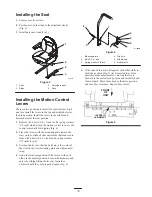
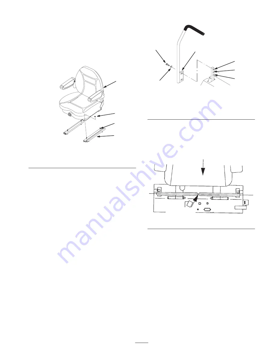
1. Remove seat from crate.
2. Position seat on the studs in the adjustable tracks
(Fig. 3).
3. Install nuts onto studs (Fig 3).
4
1
m–4817
2
3
Figure 3
1.
Seat
2.
Studs
3.
Adjustable track
4.
Nuts
Installing the Motion Control
Levers
There are two positions to install the control levers: high
and low. Install the levers in the top and middle holes for
the high position. Install the levers in the middle and
bottom holes for the low position.
1. Remove the 4 bolts (3/8 x 1 inch) and 4 spring washers
(3/8 inch) which attach the motion control levers to the
control arm shafts for shipping (Fig. 4).
2. Place the levers (with the mounting plate toward the
rear) on the outside of the control arm shaft and secure
them with 4 bolts (3/8 x 1 inch) and 4 spring washers
(3/8 inch) (Fig. 4).
3. Position the lever so that the bolts are in the center of
the slots on the lever mounting plate and tighten until
snug.
4. Align the front\rear position of the levers, with each
other, in the neutral position. Loosen the hardware and
adjust by sliding/tilting the lever(s) forward or
backward until they are properly aligned (Fig. 4).
1
2
3
m–5596
4
5
6
Figure 4
1.
Mounting plate
2.
Bolt, 3/8 x 1 inch
3.
Spring washer, 3/8 inch
4.
Top hole
5.
Middle hole
6.
Bottom hole
5. If the ends of the levers hit against each other while in
the drive position (Fig. 5) (levers rotated in as far as
possible), make adjustments by moving the levers
outward to the neutral lock position and carefully bend
them outward. Move them back to the drive position
and check for clearance. Repeat if necessary.
FRONT
OF
UNIT
LEVERS IN
ALIGNMENT
Figure 5
Summary of Contents for Z287L Z Master
Page 6: ...6 Slope Chart ...
Page 7: ...7 ...
Page 12: ...12 103 2433 106 6571 106 6570 ...
Page 55: ...55 ...

