37
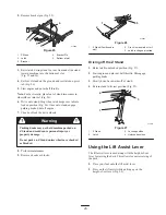
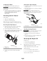
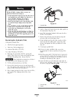
3. Grease the fittings on the push arms (Fig. 49).
m–5035
Figure 49
Where to Add Light Oil or Spray
Lubrication
Lubricate the machine in the following areas with spray
type lubricant or light oil. Lubricate every 160 hours.
•
Seat switch actuator
•
Brake handle pivot
•
Brake rod bushings
•
Motion control bronze bushings
Checking the Tire Pressure
Maintain the air pressure in the front and rear tires as
specified. Uneven tire pressure can cause uneven cut.
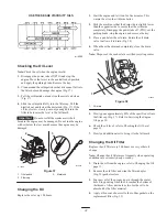
Check the pressure at the valve stem after every 50
operating hours or monthly, whichever occurs first
(Fig. 50). Check the tires when they are cold to get the most
accurate pressure reading.
Pressure: 13 psi (90 kPa) drive wheels and caster wheels
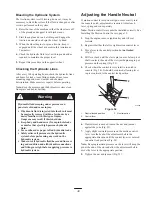
1
m–1872
Figure 50
1.
Valve stem
Servicing the Hydraulic System
Checking the Hydraulic Fluid
Check the hydraulic fluid level before engine is first
started.
Check the hydraulic fluid level after first 8 operating hours.
Check the hydraulic fluid level after every 25 operating
hours.
Fluid Type: Mobil 1 15W-50 synthetic motor oil or
equivalent synthetic oil.
Important
Use the oil specified or equivalent. Other
fluids could cause system damage.
Hydraulic System Oil Capacity: 67 oz. (2 l)
Note: There are two ways of checking the hydraulic oil.
One is when the oil is warm and one is when the oil is cold.
The baffle inside the tank has two levels depending if the
oil is warm or cold.
1. Position the machine on a level surface and set the
parking brake.
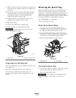
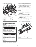
2. Clean the area around the filler neck of the hydraulic
tank (Fig. 51).
3. Remove the cap from the filler neck. Look inside to
check if there is fluid in the reservoir (Fig. 51).
4. If there is no fluid, add fluid to the reservoir until it
reaches the cold level of the baffle.
5. Run the machine at low idle for 15 minutes to allow any
air to purge out of the system and warm the fluid; refer
to Starting and Stopping the Engine, page 19.
6. Recheck the fluid level while the fluid is warm. If
required, add fluid to the reservoir until it reaches the
hot level of the baffle.
Note: The fluid level should be to the top of the hot level
of the baffle, when the fluid is warm (Fig. 51).
7. Install the cap on the filler neck.
3
1
2
4
m–5615
Figure 51
1.
Cap
2.
Baffle
3.
Cold fluid level—full
4.
Hot fluid level—full
Summary of Contents for Z287L Z Master
Page 6: ...6 Slope Chart ...
Page 7: ...7 ...
Page 12: ...12 103 2433 106 6571 106 6570 ...
Page 55: ...55 ...


