background image

54

Problem

Corrective Action

Possible Causes

5. The crankcase oil level is

incorrect.

5. Fill or drain to the full mark.

6. The fuel mixture is lean.

6. Contact your Authorized

Service Dealer.

7. Excessive loading.

7. Reduce load; use lower ground

speed.

Machine does not drive.

1. Traction belt is worn, loose or

broken.

1. Contact Authorized Service

Dealer.

2. Traction belt is off pulley.

2. Contact Authorized Service

Dealer.

3. Hydro fluid level low.

3. Add hydro fluid to reservoir.

Abnormal vibration.

1. Cutting blade(s) is/are bent or

unbalanced.

1. Install new cutting blade(s).

2. Blade mounting bolt is loose.

2. Tighten blade mounting bolt.

3. Engine mounting bolts are

loose.

3. Tighten engine mounting bolts.

4. Loose engine pulley, idler

pulley, or blade pulley.

4. Tighten the appropriate pulley.

5. Engine pulley is damaged.

5. Contact Authorized Service

Dealer.

6. Blade spindle bent.

6. Contact Authorized Service

Dealer.

Uneven cutting height.

1. Blade(s) not sharp.

1. Sharpen blade(s).

g

g

2. Cutting blade(s) is/are bent.

2. Install new cutting blade(s).

3. Mower is not level.

3. Level mower from side-to-side

and front-to-rear.

4. Gage wheel not set correctly.

4. Adjust gage wheel height.

5. Underside of mower is dirty.

5. Clean the underside of the

mower.

6. Tire pressure is incorrect.

6. Adjust tire pressure.

7. Blade spindle bent.

7. Contact Authorized Service

Dealer.

Blades do not rotate.

1. Drive belt is worn, loose or

broken.

1. Install new drive belt.

2. Drive belt is off pulley.

2. Install drive belt and check

adjusting shafts and belt guides
for correct position.

3. Deck belt is worn, loose or

broken.

3. Install new deck belt.

4. Deck belt is off pulley.

4. Install deck pulley and check

the idler pulley, idler arm and
spring for correct position and
function.

Summary of Contents for Z287L Z Master

Page 1: ...Operator s Manual Domestic English EN Form No 3329 527 Rev A Z287L Z Master with 62 SFS Side Discharge Mower Model No 74213 Serial No 230006001 and Up ...

Page 2: ...itioner 13 Filling the Fuel Tank 13 Checking the Engine Oil Level 13 Setup 14 Loose Parts 14 Installing the Drive Wheels 14 Checking the Tire Pressure 14 Installing the Seat 15 Installing the Motion Control Levers 15 Activating the Battery 16 Page Checking the Engine Oil Level 16 Checking the Side Discharge Chute 16 Checking the Leveling of the Mower Deck 16 Checking the Radiator Coolant 16 Greasi...

Page 3: ... Warning signals a hazard that may cause serious injury or death if you do not follow the recommended precautions Caution signals a hazard that may cause minor or moderate injury if you do not follow the recommended precautions This manual uses two other words to highlight information Important calls attention to special mechanical information and Note emphasizes general information worthy of spec...

Page 4: ...e Start the engine only from the operator s position Never raise deck with the blades running Never operate without the PTO shield or other guards securely in place Be sure all interlocks are functioning properly Never operate with the discharge deflector raised removed or altered unless using a grass catcher Do not change the engine governor setting or overspeed the engine Stop on level ground lo...

Page 5: ...nt set parking brake stop engine and remove key or disconnect spark plug wire Wait for all movement to stop before adjusting cleaning or repairing Clean grass and debris from cutting units drives mufflers and engine to help prevent fires Clean up oil or fuel spillage Let engine cool before storing and do not store near flame Shut off fuel while storing or transporting Do not store fuel near flames...

Page 6: ...6 Slope Chart ...

Page 7: ...7 ...

Page 8: ...Decals Safety decals and instructions are easily visible to the operator and are located near any area of potential danger Replace any decal that is damaged or lost 1 633345 1 633706 1 633462 65 2690 1 523552 1 633766 1 643401 ...

Page 9: ... 43 8480 66 1340 67 5360 104 8569 93 1122 93 7818 1 Warning read the Operator s Manual for instructions on torquing the blade bolt nut to 115 149 N m 85 110 ft lb 98 3798 98 4387 1 Warning wear hearing protection ...

Page 10: ... 0368 104 4163 1 Explosion hazard 2 No fire open flames or smoking 3 Caustic liquid chemical burn hazard 4 Wear eye protection 5 Read the Operator s Manual 6 Keep bystanders a safe distance from the battery 104 7759 104 8172 104 2449 ...

Page 11: ... 104 4164 1 Contains lead do not discard 2 Recycle 3 Wear eye protection explosive gases can cause blindness and other injuries 4 No sparks flame or smoking 5 Sulfuric acid can cause blindness or severe burns 6 Flush eyes immediately with water and get medical help fast 7 Maximum fill line 8 Minimum fill line 9 Instructions for activating the battery ...

Page 12: ...12 103 2433 106 6571 106 6570 ...

Page 13: ...then refuel such equipment on a truck or trailer from a portable container rather than from a gasoline dispenser nozzle If a gasoline dispenser nozzle must be used keep the nozzle in contact with the rim of the fuel tank or container opening at all times until fueling is complete Gasoline is harmful or fatal if swallowed Long term exposure to vapors can cause serious injury and illness Avoid prolo...

Page 14: ...alling the motion control levers Key Operator s Manual Engine Operator s Manual Parts Catalog 2 1 1 1 Read before operating machine Registration card 1 Fill out and return to Toro Installing the Drive Wheels 1 Uncrate the mower 2 Remove the wheel nuts from the rear wheel hubs 3 Align the holes Mount the drive wheels with the valve stem to the outside of the traction unit 4 Secure the wheels using ...

Page 15: ...shaft and secure them with 4 bolts 3 8 x 1 inch and 4 spring washers 3 8 inch Fig 4 3 Position the lever so that the bolts are in the center of the slots on the lever mounting plate and tighten until snug 4 Align the front rear position of the levers with each other in the neutral position Loosen the hardware and adjust by sliding tilting the lever s forward or backward until they are properly ali...

Page 16: ...l the electrolyte level is up to the upper line Fig 6 on the battery case 6 Reinstall battery filler caps 1 2 3 m 5004 Figure 6 1 Filler caps 2 Upper line 3 Lower line Charging battery produces gasses that can explode and cause serious injury Keep cigarettes sparks and flames away from battery Make sure the ignition switch is off Ventilate when charging or using battery in an enclosed space Warnin...

Page 17: ...ay result in serious injury death or drowning A rollbar is available and its use is recommended for areas where there are slopes drop offs or water To avoid loss of control and possibility of rollover Do not mow near drop offs or near water Do not mow slopes greater than 15 degrees Reduce speed and use extreme caution on slopes Avoid sudden turns or rapid speed changes 2 3 1 m 6478 Figure 8 1 Safe...

Page 18: ...ut off valve 1 4 turn to the right from the off location This uses fuel from the right side tank only When the right fuel tank is empty move the fuel shut off valve 1 4 turn to the left from the off position Close the fuel shut off valve on the front panel before transporting or storing the machine 1 Figure 12 1 Shut off valve Operating the Parking Brake Always set the parking brake when you stop ...

Page 19: ...s at a time If the engine fails to start allow a 30 second cool down period between attempts Failure to follow these instructions can burn out the starter motor 7 After the engine starts move the choke to Off Fig 15 If the engine stalls or hesitates move the choke back to On for a few seconds Then move the throttle lever to the desired setting Repeat this as required Figure 14 1 PTO On 2 PTO Off F...

Page 20: ...anding the Safety Interlock System The safety interlock system is designed to prevent the engine from starting unless You are sitting on the seat The parking brake is engaged The power take off PTO is disengaged The motion control levers are in the neutral locked position The safety interlock system also is designed to stop the engine when the traction controls are moved from the locked position w...

Page 21: ...to turn Fig 19 The farther you move the traction control levers in either direction the faster the machine will move in that direction To stop pull the motion control levers to neutral 4 m 2715 3 1 2 Figure 19 1 Motion control lever neutral lock position 2 Center unlock position 3 Forward 4 Backward Driving Backward 1 Move the levers to the center unlocked position 2 To go backward slowly pull the...

Page 22: ...g the height of cut remove the flange nut and spring disk while holding the stud with a wrench Fig 21 Note Do not remove the wheel nut and washer Fig 21 3 Select a hole so that the gage wheel is positioned to the nearest corresponding height of cut desired Fig 21 4 Reinstall the flange nut and spring disk Fig 21 5 Repeat the adjustment on the other gage wheels m 4167 1 2 3 4 5 Figure 21 1 Gage whe...

Page 23: ...lves are turned in m 6124 1 Figure 23 1 By pass valve Using a Rollover Protection System ROPS A ROPS is available and its use is recommended for areas where there are slopes drop offs or water Contact an Authorized Service Dealer for information on obtaining ROPS for your machine Important When operating a machine with ROPS always use the seat belt Transporting the Machine Use a heavy duty trailer...

Page 24: ...sudden deceleration when backing down a ramp Both maneuvers can cause the unit to tip backward Loading a unit onto a trailer or truck increases the possibility of backward tip over and could cause serious injury or death Use extreme caution when operating a unit on a ramp Use only a single full width ramp DO NOT use individual ramps for each side of the unit If individual ramps must be used use en...

Page 25: ...could cause personal injury or property damage Do not park on Z Stand unless wheels are chocked or blocked Warning 8 Perform maintenance 9 Remove chocks or blocks 1 2 3 m 5600 Figure 26 1 Z Stand Positioned in slot 2 Crack in side walk or turf 3 Latch resting on pivot tab Driving off the Z Stand 1 Raise latch to unlocked position Fig 27 2 Start engine and place at half throttle Disengage parking b...

Page 26: ... mid summer mow less frequently If you cannot mow for an extended period first mow at a high cutting height then mow again two days later at a lower height setting Cutting Speed To improve cut quality use a slower ground speed in certain conditions Avoid Cutting Too Low If the cutting width of the mower is wider than the mower you previously used raise the cutting height to ensure that uneven turf...

Page 27: ...yte Every 50 Hours Service air cleaner1 Check belts for wear cracks Check tire pressure Service spark arrester1 Every 100 Hours Replace paper air cleaner1 Change spark plug s Check hydraulic lines Change engine oil1 Check fuel system Check cooling system hoses Every 200 Hours Change oil filter1 Replace fuel filter Check engine cooling system Replace hydraulic filter Every 400 Hours Change engine c...

Page 28: ...he blade could be thrown into the operator s or bystander s area resulting in serious personal injury or death Inspect the blade periodically for wear or damage Replace a worn or damaged blade Before Inspecting or Servicing the Blades Park the machine on a level surface disengage the blade control PTO and set the parking brake Turn the ignition key to Off Remove the key and disconnect the spark pl...

Page 29: ...ufacturers may result in non conformance with safety standards Contact with sharp blade can cause serious injury Wear gloves or wrap sharp edges of the blade with a rag Warning Hold the blade end using a rag or thickly padded glove Remove the blade bolt spring disk and blade from the spindle shaft Fig 32 1 3 2 4 M 4226 3 4 5 Figure 32 1 Sail area of blade 2 Blade 3 Spring disk 4 Blade bolt 5 Cone ...

Page 30: ... clip 2 Air cleaner cover 3 Air filter 4 Carefully remove the filter from the compartment Fig 35 Cleaning the Paper Elements 1 Lightly tap the element on a flat surface to remove dust and dirt Fig 36 2 Inspect the element for tears an oily film and damage to the rubber seal Important Never clean the paper element with pressurized air or liquids such as solvent gas or kerosene Replace the paper ele...

Page 31: ... is slightly lower than the opposite side to ensure that the oil drains completely Disengage the power take off PTO set the parking brake stop the engine and remove the key 3 Place a pan below the oil drain Rotate the oil drain valve to allow oil to drain Fig 38 4 When the oil has drained completely close the drain valve Note Dispose of the used oil at a certified recycling center 1 m 5030 Figure ...

Page 32: ...lene glycol and water Cooling System Capacity 128 oz 3 8 l Danger Rotating shaft and fan can cause personal injury Do not operate the machine without the covers in place Keep fingers hands and clothing clear of rotating fan and drive shaft Shut off the engine and remove the ignition key before performing maintenance Swallowing engine coolant can cause poisoning Do not swallow engine coolant Keep o...

Page 33: ...ng the radiator cap Do not touch radiator and surrounding parts that are hot Danger Rotating shaft and fan can cause personal injury Do not operate the machine without the covers in place Keep fingers hands and clothing clear of rotating fan and drive shaft Shut off the engine and remove the ignition key before performing maintenance 1 Position the machine on a level surface stop the engine and se...

Page 34: ...e damaged hoses or the radiator Servicing the Spark Plug Check the spark plug s after every 100 operating hours Make sure that the air gap between the center and side electrodes is correct before installing the spark plug Use a spark plug wrench for removing and installing the spark plug s and a gapping tool feeler gauge to check and adjust the air gap Install a new spark plug s if necessary Type ...

Page 35: ... lines 6 Install a new filter and move the hose clamps close to the filter Fig 47 7 Wipe up any spilled fuel 8 Open the fuel shut off valve on the console 1 2 m 4384 Figure 46 1 Filter 2 Hose clamp Draining the Fuel Tank Danger In certain conditions gasoline is extremely flammable and highly explosive A fire or explosion from gasoline can burn you and others and can damage property Drain gasoline ...

Page 36: ...front of the fitting s 3 Connect a grease gun to the fitting Pump grease into the fittings until grease begins to ooze out of the bearings 4 Wipe up any excess grease Where to Add Grease Lubricate the grease fittings as shown on the Check Service Reference Aid decal Fig 48 Figure 48 Greasing the Front Caster Pivots Lubricate the front caster pivots once a year 1 Remove the dust cap and adjust the ...

Page 37: ...tor oil or equivalent synthetic oil Important Use the oil specified or equivalent Other fluids could cause system damage Hydraulic System Oil Capacity 67 oz 2 l Note There are two ways of checking the hydraulic oil One is when the oil is warm and one is when the oil is cold The baffle inside the tank has two levels depending if the oil is warm or cold 1 Position the machine on a level surface and ...

Page 38: ... forward to access the filter 3 Remove the hydraulic reservoir cap and temporarily cover the opening with a plastic bag and rubber band to prevent all hydro fluid from draining out 4 Place a drain pan under the filter remove the old filter and wipe the filter adapter gasket surface clean Fig 52 1 m 4384 Figure 52 1 Hydraulic filter 5 Apply a thin coat of hydro fluid to the rubber gasket on the rep...

Page 39: ...elieve all pressure in the hydraulic system before performing any work on the hydraulic system Make sure all hydraulic fluid hoses and lines are in good condition and all hydraulic connections and fittings are tight before applying pressure to hydraulic system Warning Adjusting the Handle Neutral If motion control levers do not align or move easily into the console notch adjustment is required Adj...

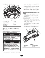
Page 40: ...e made with drive wheels turning 1 Raise the frame and block up the machine so drive wheels can rotate freely 2 Disconnect electrical connector from the seat safety switch Temporarily install a jumper wire across terminals in the wiring harness connector 3 Slide seat forward disconnect prop rod and tilt seat fully forward Setting the Right hand Hydraulic Pump Neutral 1 Start the engine open thrott...

Page 41: ... operate this unit with jumper installed and seat switch bypassed Warning 7 After both pump neutrals are set shut off the machine 8 Remove jumper wire from wire harness connector and plug connector into seat switch 9 Reinstall prop rod and lower the seat into position Adjusting the Tracking The right hand pump has a knob for adjusting the tracking Important Adjust the handle neutral and hydraulic ...

Page 42: ...the hole Two threads or less should be showing Fig 59 5 If more than two threads are showing remove the nut and install the washer between the hub and nut Fig 59 6 Torque the slotted nut to 125 ft lb 170 N m Fig 59 7 Tighten the nut until the next set of slots line up with the hole in the shaft Fig 59 8 Install the cotter pin 3 m 4638 1 2 4 Figure 59 1 Slotted nut 2 Two threads or less showing 3 H...

Page 43: ...s can be checked with the same procedure as Checking for Bent Blades page 28 12 Install the anti scalp rollers for proper height of cut and tighten them securely 13 Raise the deck lift lever to the transport position Fig 60 14 Adjust the compression springs by turning the front spring nuts so that the distance between the two large washers is 11 inches 279 mm Fig 61 Clockwise will shorten the spri...

Page 44: ...from the wire harness Fig 63 3 Remove the PTO drive belt from the rear idler arm and front idler pulley assembly Remove the PTO drive belt Fig 63 4 Place the new drive belt over the clutch around the rear idler pulley installed into the rear idler arm assembly installed into the front idler pulley assembly and onto the top center pulley Fig 63 Important Check the amount of twist in the belt betwee...

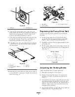
Page 45: ...1 4 inch 3 7 mm Replacing the Pump Drive Belt Check pump drive belt for wear after every 50 hours of operation 1 Pull the spring loaded idler down and remove the traction belt from the engine and hydro pump pulleys Fig 68 Remove the belt between the pulleys 2 Install the new belt around the engine and hydro pump pulleys Fig 68 3 Pull the spring loaded idler down and align it below the traction bel...

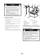
Page 46: ... blade type Fan 30 amp blade type 1 To gain access to the main fuse raise the seat To gain access to the fan and alternator fuses raise the seat and tilt the engine cover forward 2 To replace a fuse pull out on the fuse to remove it Fig 70 m 3653 2 1 Figure 70 1 Fan 30 amp 2 Main 20 amp Servicing the Battery Battery posts terminals and related accessories contain lead and lead compounds chemicals ...

Page 47: ... with 2 bolts 1 4 x 3 4 inch 2 washers 1 4 inch and 2 locknuts 1 4 inch Fig 72 5 Slide the red terminal boot onto the positive red battery post 6 Secure battery with J bolts hold down clamp and 2 washers 1 4 inch and 2 wing nuts 1 4 inch Fig 72 1 9 5 2 6 7 10 4 3 8 11 7 m 5598 Figure 72 1 Battery 2 Terminal boot 3 Positive battery cable 4 Negative battery cable 5 Ground wire 6 Bolt 1 4 x 3 4 inch ...

Page 48: ...d water into each battery cell until the level is up to the upper line Fig 71 on the battery case Important Do not overfill the battery because electrolyte sulfuric acid can cause severe corrosion and damage to the chassis 5 Wait five to ten minutes after filling the battery cells Add distilled water if necessary until the electrolyte level is up to the upper line Fig 71 on the battery case 6 Rein...

Page 49: ...flector 7 Place behind deck edge before installing bolt 8 Hook end of spring Waste Disposal Engine oil hydraulic oil and engine coolant are pollutants to the environment Dispose of these according to your state and local regulations Mercury Tilt Switch The tilt switch on this unit is located under the seat Tilt the seat up to gain access The tilt switch on this unit contains mercury a hazardous ma...

Page 50: ... waste or waters Management and disposal practices must be within relevant federal state or local laws Return the switch to your Toro dealer if it is faulty and is being replaced or if the unit containing the switch is no longer operating and is being scrapped If the switch is damaged or broken open use extreme caution in handling Call your local waste management authority or Toro Customer Service...

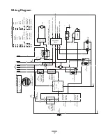
Page 51: ...ORANGE BLACK PK BK PINK BLACK VIO GND PK WIRE COLOR CODES GND NEUTRAL SW5 LT BU BRAKE SW3 SHOWN WITH PARK BRAKE DISENGAGED P1 A PK BK K1 KILL RELAY DK BU SW6 SEAT SW SHOWN WITH OPERATOR IN SEAT K3 FAN RELAY F1 20A BATTERY GND OR ENGINE KILL TEMPERATURE SWITCH BK NOTE THAT MOST OF THE WIRE COLORS CHANGE AT THE ENGINE CONNECTOR Y R YELLOW RED BU R DK GN BK DARK GREEN DK GN DARK GREEN BLACK LT GN DEL...

Page 52: ...ollow mixing instructions from the stabilizer manufacturer Do not use an alcohol based stabilizer ethanol or methanol Note A fuel stabilizer conditioner is most effective when mixed with fresh gasoline and used at all times B Run the engine to distribute conditioned fuel through the fuel system 5 minutes C Stop the engine allow it to cool and drain the fuel tank refer to Draining the Fuel Tank pag...

Page 53: ...ncorrect 5 Install new correctly gapped spark plugs 6 Dirt in fuel filter 6 Replace fuel filter 7 Dirt water or stale fuel is in fuel system 7 Contact Authorized Service Dealer Engine loses power 1 Engine load is excessive 1 Reduce ground speed g 2 Air cleaner is dirty 2 Clean air cleaner element 3 Oil level in crankcase is low 3 Add oil to crankcase 4 Cooling fins and air passages under engine bl...

Page 54: ...ppropriate pulley 5 Engine pulley is damaged 5 Contact Authorized Service Dealer 6 Blade spindle bent 6 Contact Authorized Service Dealer Uneven cutting height 1 Blade s not sharp 1 Sharpen blade s g g 2 Cutting blade s is are bent 2 Install new cutting blade s 3 Mower is not level 3 Level mower from side to side and front to rear 4 Gage wheel not set correctly 4 Adjust gage wheel height 5 Undersi...

Page 55: ...55 ...
Page 56: ...vered There is no other express warranty except for special emission system coverage on some products This express warranty does not cover the following Cost of regular maintenance service or parts such as filters fuel lubricants tune up parts blade sharpening brake and clutch adjustments Any product or part which has been altered or misused or required replacement or repair due to normal wear acc...

Reviews: