39
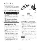
2. Pump grease into zerk until it oozes out around top
bearing.
3. Remove grease zero in hole. Reinstall hex plug and
cap.
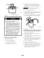
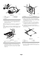
Where to Add Grease
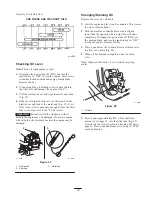
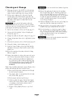
Lubricate the grease fittings as shown on the CHECK
SERVICE REFERENCE AID decal (Fig. 38).
Figure 38
Where to Add Light Oil or Spray
Lubrication
Lubricate the machine in the following areas with spray
type lubricant or light oil. Lubricate every 160 hours.
•
Seat switch actuator.
•
Brake handle pivot.
•
Brake rod bushings.
•
Motion control bronze bushings.
Greasing the Bearings
The cutting unit must be lubricated regularly. Refer to the
Service Interval Chart on page 29. Grease with No. 2
general purpose lithium base or molybdenum base grease.
Important
Make sure cutting unit spindles are full of
grease daily.
1. Stop the engine, set the parking brake, remove the key
and disconnect the spark plug wire(s) from the spark
plug(s).
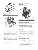
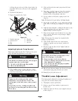
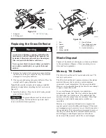
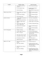
2. Grease the fittings on the three spindle bearings until
grease comes out lower seals (Fig. 39).
3. Grease the fittings on the push arms(Fig. 39).
M-5035
Figure 39
Tire Pressure
Maintain the air pressure in the front and rear tires as
specified. Uneven tire pressure can cause uneven cut.
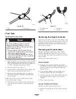
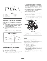
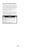
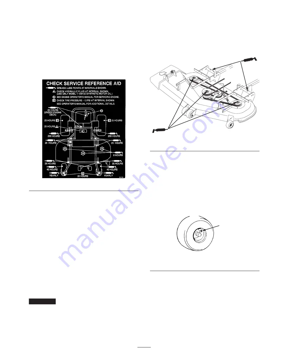
Check the pressure at the valve stem after every 50
operating hours or monthly, whichever occurs first
(Fig. 40). Check the tires when they are cold to get the
most accurate pressure reading.
Pressure: 13 psi (90 kPa) drive wheels and castor wheels.
1
m–1872
Figure 40
1.
Valve stem
Wheel Hub Slotted Nut
Check after every 500 operating hours.
The slotted nut needs to be torqued to 125 ft–lbs (169.5
N
m).
1. Stop the engine, set the parking brake, remove the key
and disconnect the spark plug wire(s) from the spark
plug(s).
2. Remove cotter pin.

