7.
Run the machine at low idle for 15 minutes to allow
any air to purge out of the system and warm the fluid;
refer to
Starting and Shutting Off the Engine (page 24)
.
Note:
Check the fluid level while the fluid is warm.
The fluid should be between cold and hot.
8.
If required, add fluid to the hydraulic tank.
Note:
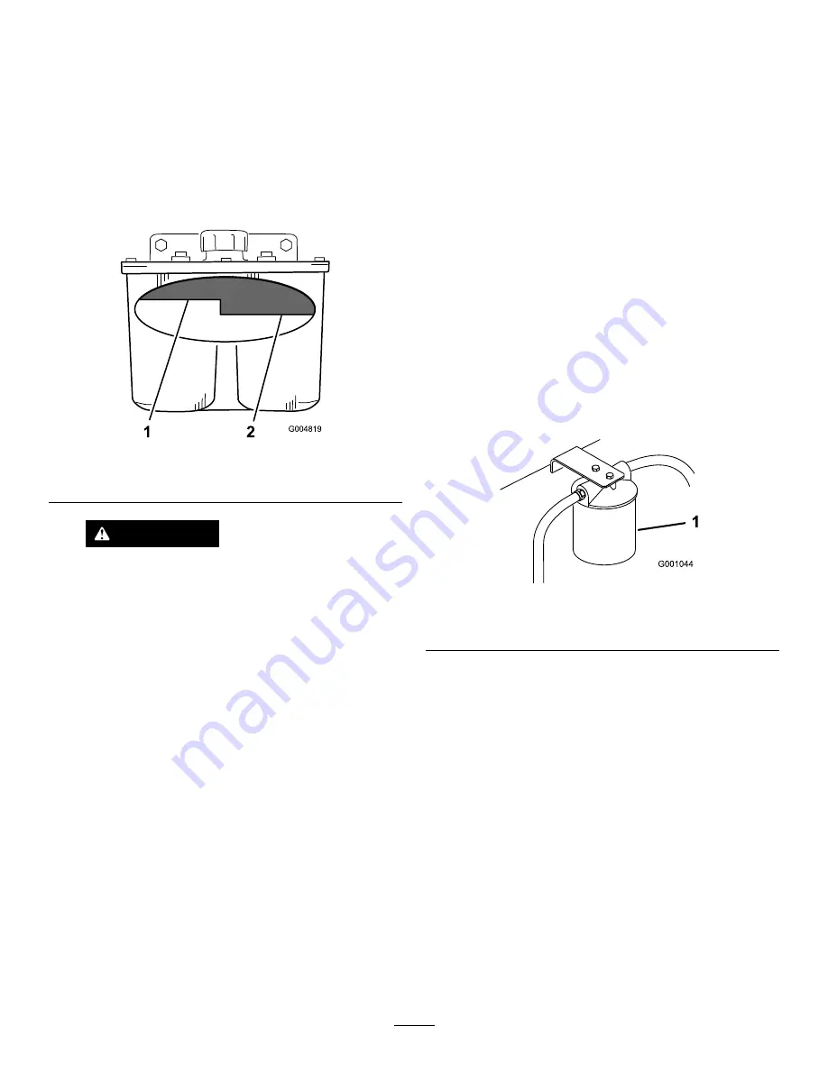
The fluid level should be to the top of the hot
level of the baffle, when the fluid is hot (
).
9.
Install cap on filler neck.
g004819
Figure 91
1.
Hot fluid level-full
2.
Cold fluid level-full
WARNING
Hydraulic fluid escaping under pressure can
penetrate skin and cause injury.
•
If hydraulic fluid is injected into the skin it
must be surgically removed within a few
hours by a doctor familiar with this type
of injury. Gangrene may result if this is
not done.
•
Keep body and hands away from pin hole
leaks or nozzles that eject high-pressure
hydraulic fluid.
•
Use cardboard or paper to find hydraulic
leaks.
•
Safely relieve all pressure in the hydraulic
system before performing any work on the
hydraulic system.
•
Make sure that all hydraulic-fluid hoses
and lines are in good condition and all
hydraulic connections and fittings are
tight before applying pressure to hydraulic
system.
Replacing the Hydraulic Filter and Fluid
Service Interval:
After the first 25 hours
Every 250 hours—Change the hydraulic filter and
hydraulic fluid when using Mobil
®
1 fluid.
Every 500 hours—Change the hydraulic filter and
hydraulic fluid when using Toro
®
HYPR-OIL
™
500
hydraulic fluid.
Use summer filter above 0°C (32°F)
Use winter filter below 0°C (32°F)
1.
Disengage the blade-control switch (PTO), move the
motion-control levers to the N
EUTRAL
-
LOCK
position,
and engage the parking brake.
2.
Shut off the engine, remove the key, and wait for all
moving parts to stop before leaving the operating
position.
Important:
Do not substitute automotive oil filter
or severe hydraulic system damage may result.
3.
Place drain pan under filter, remove the old filter and
wipe the filter adapter gasket surface clean (
g001044
Figure 92
1.
Hydraulic filter
4.
Remove the right hydraulic line that comes into the
adapter (
5.
Allow the fluid to drain out of the system into the
drain pan.
6.
Install the right hydraulic line to the adapter (
).
61
Summary of Contents for Z593-D Z Master 74264TE
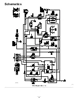
Page 75: ...Schematics g012068 g012068 Wire Diagram Rev A 75 ...
Page 76: ...Notes ...
Page 77: ...Notes ...
Page 78: ...Notes ...


