background image

3. Rock the ring gear back and forth to get a feel for the amount of ba klash pre ent (usually around .008).

This step will allow you to check during re-assembly that the bearing adjusters are in their correct

positions and are not one turn off. (When in doubt use a dial indicator and stand to measure the before

and after backlash).

4. Remove the adjuster locks, bearing cap bolts and caps.

5. Mark the diff rential b a ing races so that they can be re-installed on the same side.

6. Lift the differenti l case from the third member.

7. Mark the ring gear in relation to the differential case.

8. R

 th  ring gear

9. Remo   e pinion shaft.

10. Remove  he spid r gears and side gears and all thrust washers.

11. Proceed to the next section entitled Examination and Preparation of the Parts.

EXAMINATION AND PREPARATION OF THE PARTS AND THE DIFFERENTIAL CASE—ALL MODELS

EXAMINATION OF THE PARTS

1. Check the tw  large side gear thrust washers for wear, cracks, warping or galling  If they are not in

e cellent cond tion, replace them  The small washers under the spider gears will not be used.

2. Examine the pinion shaft. If it is worn by more than .002 where the side gears were located, purchase a

new one from your dealer.

3. Check the hardness of the pinion shaft. In many instances we have found that the stock factory shaft is

somewhat soft. Try to scratch a groove in it with a file near the center. If you can do so, the shaft is

soft. If the file tends to slide and not cut, the shaft hardnes  is probably ac eptable. If it is soft r place

it, and also be sure to check the new shaft. If the old shaft is worn under the spider gears, definitely

replace it.

4. Thoroughly clean the differential housi g to remove any old dirt and metal particles.

5. If the installat on is in the front d fferential, now would be the time to inspect/replace the inne  axle seals.

6. Examine the differential case and  earings. If there are any chips or cracks  n the case, and/or the

b ar ngs are worn, replace them—but remember that the ring and pinion backlash and bearing pre-load will

need to be set up again.

7. If your differential has a thrust block and it is to be re-used (Jeep AMC-20, for example), examine the

block and be sure that it is in good condition. If it needs to be replaced, be sure to set up the axle shaft

end-play again (see your shop manual).

CHECKING CASE TOLERANCES

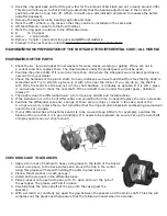
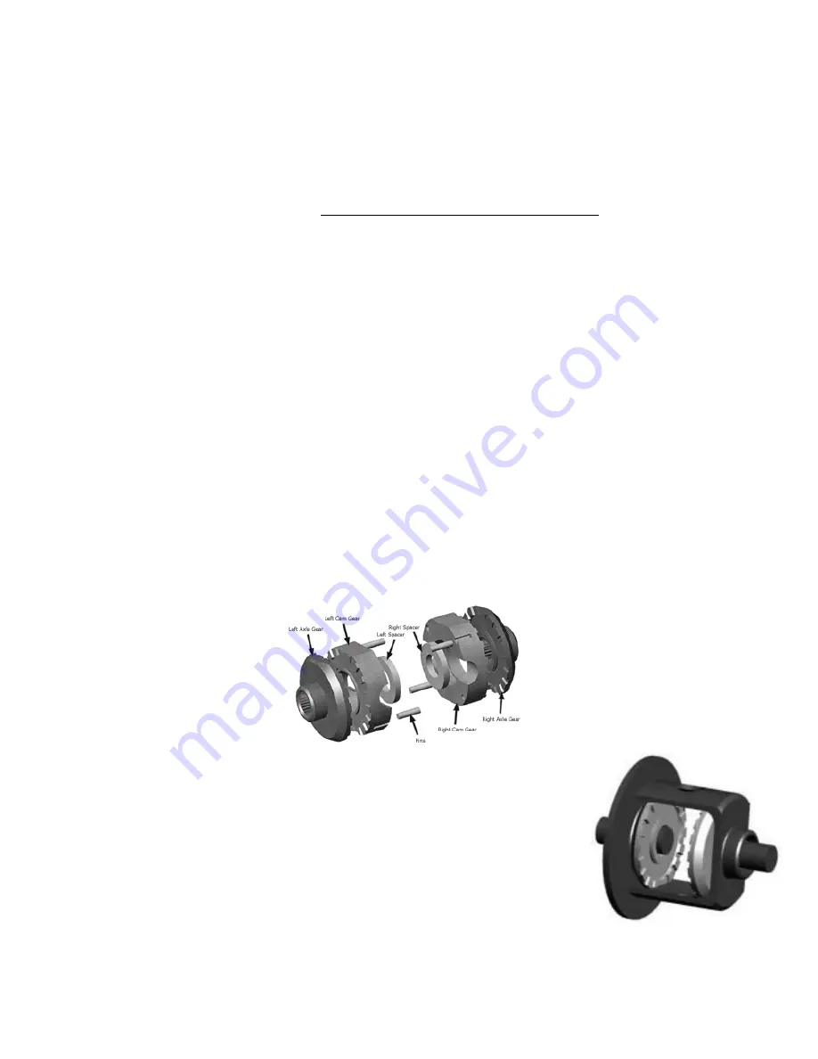
1. Apply a thin coat of medium to heavy axle grease to the teeth of the Aussie

Locker axle gears, to the back surface and around the hub in the center.

Using this grease will help with holding the parts in place later on.

2. Place a thrust washer on each axle ge r.

3. Install both axle gears in the differential case.

4. Place a spacer onto each axle gear, with th  open end over the hub of

the axle gear. The grease will hold it in place.

5. Carefully slide the pinion shaft all the way into the case (past the

spacers).

6. With a screwdr ver, carefully pry apart the gap between the spacers and the pinion shaft. This step will

compress out the grease and help assure that the following measurement is accurate.


Th s  tep wi l allow you  o check dur ng  e ass m ly t at the bearing adjusters ar   n the r correct

posi ions a d are not one  urn o f. (Wh n in doubt use a dial  ndicato  and stand  o measu e the b

and after bac lash .

Remove  he adjus e  


5. Mark the dif erential bearing races  o that th y c n be 


6. Lift t e d ferentia  c se from the third member.

7. Ma k the ring gear in relation to the d fferentia  

8. Rem ve the r ng gear

9. Remove the pinion sh

1 Remove the spider gear  


11. Proceed to the nex  sect n entitled Examinat on and Preparati


exce l nt cond tion,  ep ace them  The small was ers  nder th  spider gea s w ll n t be u ed.

Examine  he pinion shaft  I   t is worn by more than . 02 where the side ge r  were l cated  


new one from  our deale

Che k the hardness of th  


somewhat soft. Try  o scratch a groove  n  t with a file ne r  he center. If you can do so  the sh ft is

soft  If the file  ends to slide  nd not cut  the sh ft ha dness is  robab   cceptab e   f i  is soft rep

it, a d also be sure to check he new shaf . f the o d shaft is worn unde the spider ear

efin tely

r

lace it.

horou h  


5. If the insta ation is in the  ront differential, now wou d  e the t me  o  nspect/repla  


6. Exam ne the d ffere t al case and bearings  If there ar  any ch ps or cracks in  he case  a d/or the

bearings are worn  repla e th m—but reme ber that the ring and pinion backlash and b ar ng pre-l


need to be set up again

If yo r di ferentia  has a 


block  nd be sure that i   s in good condi on. If it needs to be replace , be s re to set  p the axle sh

end-p ay  ga n ( ee your shop manual


Locke

xle gear , to the back surface and around the hub in he center.

Using  h s g ease will help with holding the parts in pla e la er on.

P ace a th u t washe  on each axle ge r.

3. Insta   oth ax e gear  in the d fferential 

4. Place   spa er onto each axle gear, with the 


the a l  gear.  he g ease wi l hold   i  p ace

Carefu ly slid   he pinion sha t a l the  ay in  


spacers)

With a  c


com r ss ou  the g ease and he  assure t at  he fo low ng measurement is a cura e


Summary of Contents for Aussie Locker series

Page 1: ...ocker equipped vehicle We suggest that you read these instructions before beginning your installation to familiarize yourself with the steps performed for your particular axle type and to determine wh...

Page 2: ...bearing pre load and the ring and pinion backlash which generally must be done by a shop having the right knowledge and tools As with most factory differentials the Aussie Locker is designed to be in...

Page 3: ...e two types of axles have several differential designs including 1 C Clip axle shaft retention Ford 8 8 Spicer 35 Land Cruiser with thrust block etc 2 Bearing retainer axle shaft retention Jeep AMC 20...

Page 4: ...es sliding the axle shafts in and out easier 1 Remove the pinon shaft 2 Remove the thrust block if present 3 Push the axle shafts inward and remove the C clips 4 Pull each axle shaft out by about thre...

Page 5: ...rta t t put h se hims ba k in h s m l at n nd rd u n r ssembly 5 Ma k the diff r nti l b ring ut r r s s th s is ming ut s th t th n b r inst ll d n th id s 6 M rk t ng ge t s l ati R m th in g r fr m...

Page 6: ...e Aussie Locker axle gears to the back surface and around the hub in the center Using this grease will help with holding the parts in place later on 2 Place a thrust washer on each axle ge r 3 Install...

Page 7: ...stall the C clip on the end of the axle shaft with the points facing downward 3 Pull snap the axle shaft outward to seat the C clip onto the hub of the axle gear 4 Carefully insert one of the cam gear...

Page 8: ...ching the t cam gear with a g etwee the gh han teet Remov the too ver t ng shou d just s there he d n p asse b y may n e to be he d in p ace during the o owing steps W h the e t ax e s owly otate the...

Page 9: ...into the bottom of the slot and the other end should snap over the step on the end of the pin 8 Repeat step 7 for the remaining three pins and springs The assembly of the locker itself is now complete...

Page 10: ...o k m INST LL THE DIFFERENTI L C SE REMO BLE C RRIER THIRD MEMBER j h r r n m s b n r m r T r M m f n f h n n r sh m n f r h r r s h f n n h Th ff n r n th r h s n r n r ss h m r j te s n h h s th e s...

Page 11: ...ke turns slowly at first Remember that if you power around a turn that the inside powered wheel will spin up more easily than before because weight s transferring off it as the vehicle leans outward 3...

Page 12: ...some Toyota differentials it may be necessary to file down casting flashing and case irregularities prior to fitting parts 3 Some Ford Dana 44 front installations may require minor grinding in the ca...

Reviews: