background image

Pflege und Service

DE

EN

9.4 Wechsel Propeller und Finne

Wechsel Propeller

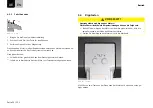
WARNUNG!

Verletzungsgefahr durch Propeller!

Mittlere oder schwere Körperverletzungen können die Folge sein.

Schalten Sie bei Arbeiten am Propeller das System stets über den Haupt-

schalter ab.

Ziehen Sie den Not-Aus-Magnetchip ab.

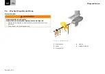
1

3

2

4

5

Abb. 26: Propellerbefestigung

1

Wellenanode

4

Scheibe

2

Splint

5

Axialdruckscheibe

3

Kronenmutter

Seite 46 / 121

Summary of Contents for Cruise 10.0 T

Page 1: ...Cruise 10 0 T Originalbetriebsanleitung Deutsch English...

Page 2: ...eingehend gepr ft Bitte nehmen Sie sich die Zeit diese Bedienungsanleitung gr ndlich durchzulesen damit Sie das System sachgem behandeln k nnen und langfristig Freude an ihm haben Wir bem hen uns die...

Page 3: ...er und Finne 18 5 3 Montage der Pinne 20 5 4 Trimmung des Motors 21 5 5 Batterieversorgung 22 5 5 1 Anmerkungen zur Batterieversorgung 23 5 5 2 Anschluss Cruise 10 0 T an zwei Torqeedo Power 48 5000 B...

Page 4: ...42 9 3 Service Intervalle 44 9 3 1 Ersatzteile 45 9 3 2 Korrosionsschutz 45 9 4 Wechsel Propeller und Finne 46 9 5 Wechsel der Opferanoden 48 9 6 Lagerung des Motors 49 10 Allgemeine Garantiebedingung...

Page 5: ...n der N he des Cruise Systems aufbewahrt werden Achten Sie darauf immer eine aktuelle Version der Anleitung zu verwenden Die ak tuelle Version der Anleitung kann im Internet auf der Website www torqee...

Page 6: ...Risiko Leichte oder mittlere K rperverletzungen oder Sachsch den k nnen die Folge sein wenn das Risiko nicht vermieden wird Hinweise HINWEIS Hinweise welche unbedingt beachtet werden m ssen Anwendert...

Page 7: ...n jedem Cruise System ist ein Typenschild zur Erfassung der Eckdaten laut Maschi nenrichtlinie 2006 42 EG angebracht Abb 1 Typenschild 1 Artikelnummer und Motoren Typ 2 Seriennummer 3 Betriebsspannung...

Page 8: ...erung Pinne mit integriertem Display und Anschlusskabel Propeller mit Befestigungssatz 5 teilig Finne mit drei Befestigungsschrauben M6 aus Aluminium Not Aus Magnetchip Kabelsatz mit Hauptschalter und...

Page 9: ...mpf nger im Schaftkopf 9 Halbringanoden 2 Pinne 10 Wellen Opferanode 3 Spiegelhalterung 11 Trimmbolzen zur Fixierung der Rast position des Motors 4 Knebelschraube 12 Ringanoden an Spiegelhalterung 5 B...

Page 10: ...51 2 cm TL 63 9 cm TXL Propellerdrehzahl bei max Drehzahl 1400 U min Steuerung Pinne Lenkung 45 Kippvorrichtung Elektrohydraulischer Tilt mit berlast schutz Auflaufschutz durch Hydrau likventile Trimm...

Page 11: ...en HINWEIS Lesen und beachten Sie unbedingt die Sicherheits und Warnhinweise in die ser Anleitung Lesen Sie diese Anleitung sorgf ltig bevor Sie das Cruise System in Betrieb nehmen Fehlende Ber cksich...

Page 12: ...Cruise Systems au erhalb von Wasserfahrzeugen 4 1 4 Vor dem Gebrauch Das Cruise System d rfen nur Personen mit entsprechender Qualifizierung hand haben die die erforderliche k rperliche und geistige E...

Page 13: ...tausl sen des Not Stopps Tod oder schwere K rperverletzungen k nnen die Folge sein Befestigen Sie die Leine des Not Aus Magnetchips am Handgelenk oder der Rettungsweste des Bootsf hrers GEFAHR Lebensg...

Page 14: ...ichend bel fteten Backskiste WARNUNG Verletzungsgefahr durch ungleiche Batterien Schwere K rperverletzungen oder Tod k nnen die Folge sein Verschalten Sie nur identische Batterien Hersteller Kapazit t...

Page 15: ...sundheitssch den k nnen die Folge sein Heben Sie das Cruise System nicht alleine und verwenden Sie geeignetes He bezeug VORSICHT Quetschgefahr durch Kippen des Motors Leichte oder mittelschwere K rper...

Page 16: ...atterien darauf erst die schwarze Minus leitung und danach die rote Plusleitung abzunehmen Vertauschen Sie niemals die Polarit t VORSICHT Verbrennungsgefahr durch hei en Motor Leichte oder mittelschwe...

Page 17: ...Knebelschrauben dienen als Montagehilfe Verwenden Sie deshalb stets die M12 Schrauben zur Fixierung des Cruise Systems im Betrieb VORSICHT Verletzungsgefahr durch schwere Lasten Gesundheitssch den k n...

Page 18: ...eposition Beachten Sie beim Anbau des Motors an das Boot dass der Propeller mindestens 10 30 mm unterhalb des Bootsrumpfes angebracht ist 5 2 Montage Propeller und Finne Montage Finne WARNUNG Verletzu...

Page 19: ...uckscheibe 3 Kronenmutter 1 Stecken Sie die Axialdruckscheibe mit der Fase zum Motor auf die Welle 2 Stecken Sie den Propeller bis zum Anschlag auf die Welle auf 3 Legen Sie die Scheibe 4 zwischen und...

Page 20: ...tage der Pinne m ssen Sie folgende Handlungsschritte ausf hren 1 Schlie en Sie die Kabel 4 inklusive Fixierung an 2 Setzen Sie die Pinne 3 ein 3 Montieren Sie die Pinne mit zwei M8x16 Schrauben 2 sowi...

Page 21: ...as Kippen kann der Motor aus dem Wasser genommen werden z B bei Nichtbenutzung oder bei Anlanden des Bootes sowie geringer Wassertiefe Durch das Trimmen l sst sich der Motor optimal zur Wasseroberfl c...

Page 22: ...eller Kapazit t und Alter Verschalten Sie nur Batterien mit identischem Ladestand WARNUNG Verletzungsgefahr durch Kurzschluss Schwere K rperverletzungen oder Tod k nnen die Folge sein Legen Sie metall...

Page 23: ...12 V und 100 Ah hat also eine Nennkapazit t von 1 200 Wh F r Blei S ure Blei Gel und AGM Batterien gilt dass die so berechnete Nennka pazit t nicht vollst ndig zur Verf gung gestellt werden kann Dies...

Page 24: ...en Sie deshalb den Cruise 10 0 T mit allen bei den Power 48 5000 wie in Abb 11 Schaltplan Power 48 5000 gezeigt 5 5 3 Anschluss Cruise 10 0 T an eine Torqeedo Power 48 5000 Bat terie 1 Demontieren Sie...

Page 25: ...Sie zur Seriellen Verschaltung der Batterien das Bleibank Kabelset Cruise 10 0 Art Nr 1940 00 siehe Kapitel 11 Zubeh r Sollten Sie den Cruise 10 0 T mit nur zwei Blei Batterien Gel AGM betreiben m s s...

Page 26: ...er z B Fischfinder Licht Radios etc nicht an die gleiche Batteriebank mit der die Motoren betrieben werden an Torqeedo empfiehlt f r andere Verbraucher immer eine separate Batterie anzu schlie en 5 6...

Page 27: ...e Ladestand in Prozent 3 Geschwindigkeit ber Grund 2 Verbleibende Reichweite bei aktueller Geschwindigkeit 4 Aktueller Leistungsverbrauch in Watt 1 2 3 4 5 6 Abb 15 Multifunktionsanzeige Setup Men 1 D...

Page 28: ...ld das Symbol Error und ein Fehlercode wird angezeigt Der Code zeigt die ausl sende Kompo nente sowie den Fehler der Komponente an Details zu den Fehler codes finden Sie in Kapitel Fehlermeldungen 5 6...

Page 29: ...M glichkeiten umfasst erfolgt die Auswahl des Wertes mit dem Gashebel 6 Best tigen Sie die Auswahl mit der Taste Setup Die Auswahl f hrt zum Verlassen des Setup Men s HINWEIS Bitte beachten Sie dass z...

Page 30: ...und Stunden w hlen 3 Best tigen Sie Ihre Auswahl mit der Taste Setup Es wird die Einstellung der Geschwindigkeitsanzeige angezeigt 4 W hlen Sie mit der Taste CAL die Einheit in der die Geschwindigkeit...

Page 31: ...WEIS Pr fen Sie die Funktion des Not Stopps vor jedem Start bei geringer Motor leistung Bet tigen Sie in Notsituationen sofort den Not Stopp Nutzen Sie den Not Stopp bei hoher Leistung nur in Notsitua...

Page 32: ...nalysieren und ber cksichtigen kann siehe Kapitel 9 2 Kalibrierung mit Fremdbatteri en W hrend der Fahrt misst der Bordcomputer die verbrauchte Energie und bestimmt damit die Ladung der Batterie in Pr...

Page 33: ...iden Motor starten 1 Schalten Sie den Motor ein indem Sie die Ein Aus Taste 1 f r eine Sekunde dr cken 2 Legen Sie den Not Aus Magnetchip auf die Pinne auf 3 Bewegen Sie die Pinne aus der Neutralstell...

Page 34: ...Motor grunds tzlich aus dem Wasser genommen werden In Salz oder Brackwasser muss der Motor mit Frischwasser abgesp lt werden 6 4 Kipptasten VORSICHT Quetschgefahr durch Kippen des Motors Leichte oder...

Page 35: ...Abb 23 Tasten Der Motor wird hydraulisch nach oben gekippt Abb 24 Motor vollst ndig hochgekippt Herunterkippen 1 Dr cken Sie auf die rechte Taste an der Pinne siehe Abb 23 Tasten Der Motor wird hydrau...

Page 36: ...1 im Uhrzeigersinn Um den Widerstand zu reduzieren bewegen Sie den Hebel 1 gegen den Uhrzeiger sinn ber die unter dem Hebel liegende Mutter 2 mit der Schl sselweite 10 mm l sst sich die Grundeinstellu...

Page 37: ...Motors beim Trailern nicht die Kippsperre an der Spiegelhalterung Nutzen Sie beim Trailern eine geeignete St tze wie beispielsweise Kanth l zer o zur Sicherung des Schaftes Beim Trailern des Bootes m...

Page 38: ...ckierung l sen und Propeller von Hand eine Umdrehung weiter drehen Batterien wieder an das System anschlie en E06 Spannung am Motor zu niedrig Niedriger Ladestand der Batterie Motor kann ggf aus Stopp...

Page 39: ...librierung durchf hren siehe E21 Sollte der Fehlercode mehr mals auftreten kontaktieren Sie den Torqeedo Service E23 Wertebereich falsch Neukalibrierung durchf hren siehe E21 E30 Kommunikationsfehler...

Page 40: ...wer 48 5000 Anzeige Ursache Was ist zu tun E70 ber Untertemperatur beim Laden Ursache f r Verlassen des Temperaturbereichs entfernen ggf zum Abk h len Ladeger t entfernen Batterie aus und einschalten...

Page 41: ...hler Batterie Es wurden Batterien mit unterschiedlichen Software Versionen miteinander verbunden Torqeedo Service kontaktieren E84 Batterieanzahl stimmt nicht mit Enumeration berein Verbindungen der B...

Page 42: ...smitteln gerei nigt die Kunststoffoberfl chen k nnen mit Cockpit Spray behandelt werden Zur Reinigung des Motors k nnen Sie alle f r Kunststoff geeigneten Reinigungsmit tel entsprechend der Vorgabe de...

Page 43: ...ge Laufzeiten er geben Falls Sie das Spannungsniveau der Batteriebank w hrend der Kalibrierungs fahrt verfolgen wollen k nnen Sie das Multifunktions Display als Span nungsanzeige verwenden Gehen Sie w...

Page 44: ...entiert sind Service T tigkeiten Vor jeder Benutzung Halbj hrlich oder nach 100 Be triebsstunden Alle 5 Jahre oder nach 700 Be triebsstunden was zuerst eintritt Batterien und Batteriekabel Vollst ndig...

Page 45: ...n der im Cruise System verbauten Materialien sind wie f r maritime Produkte im Freizeitbereich blich als seewasserbest ndig nicht als seewasserfest klassifiziert Um Korrosion trotzdem zu vermeiden Bew...

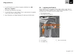
Page 46: ...opeller Mittlere oder schwere K rperverletzungen k nnen die Folge sein Schalten Sie bei Arbeiten am Propeller das System stets ber den Haupt schalter ab Ziehen Sie den Not Aus Magnetchip ab 1 3 2 4 5...

Page 47: ...cheibe 4 5 Ziehen Sie den Propeller ab HINWEIS Achten Sie bei der Demontage und Montage darauf dass die Axialdruckscheibe 5 nicht verloren geht 6 Sichtpr fung auf Besch digungen und Fremdk rper z B An...

Page 48: ...otor vor Korrosion F r den Wechsel muss der Propeller nicht demontiert werden Insgesamt sind f nf Opferanoden zu wechseln Die Anoden m ssen satzweise getauscht werden 3 4 1 2 2 1 Abb 28 Anoden 1 Halbr...

Page 49: ...hten Seite 4 Neue Opferanoden der Spiegelhalterung 6 einsetzen und festschrauben 9 6 Lagerung des Motors Wenn Sie den Motor in hochgekippter Position lagern m chten nutzen Sie zur Si cherung den Hebel...

Page 50: ...etauscht werden entscheidet Torqeedo Distributoren und H ndler die Reparaturarbeiten an Torqeedo Motoren durchf hren haben keine Vollmacht rechtsverbindliche Erkl rungen f r Torqeedo abzugeben Von der...

Page 51: ...qeedo Service halten Sie bit te Ihr Service Checkheft Ihren Kaufbeleg und einen ausgef llten Garantieschein bereit Der Vordruck f r den Garantieschein liegt dieser Anleitung bei Die Anga ben im Garant...

Page 52: ...t 2900 W f r Power 48 5000 Ladeleistung 2900 W l dt die Power 48 5000 in 2 Stunden von 0 auf 100 wasserdicht IP65 1969 00 Kabelsatz f r Bleibatterien Kabelsatz f r die Umr stung von Cruise 10 0 Motor...

Page 53: ...00 Kabelbr cken AGM Gel Batterien Kabelbr cken zum Betrieb des Cruise 10 0 T mit AGM Gel Batterien Be stehend aus 4 Kabel 40 cm L nge 35 mm mit Polschuh Anschluss 9259 00 Finne f r Cruise 10 0 T Sch t...

Page 54: ...umweltvertr glich zu entsorgen Es ist auch m glich dass Ihre nationalen Gesetze dies vorschreiben Bitte stellen Sie daher eine fachgerechte Entsorgung des Systems nach den in Ihrem Land geltenden Vor...

Page 55: ...Wir empfehlen die Batterien bzw Akkumulatoren nicht ber den normalen Restm ll sondern in einer getrennten Sammlung zu ent sorgen Es ist auch m glich dass Ihre nationalen Gesetze dies vorschreiben Bit...

Page 56: ...sch fts und Gewerbebe reiche sowie Kleinbetriebe IEC 61000 6 3 2006 A1 2010 RICHTLINIE 2014 35 EU DES EUROP ISCHEN PARLAMENTS UND DES RATES vom 26 Februar 2014 zur Harmonisierung der Rechtsvorschrifte...

Page 57: ...rqeedo GmbH Anschrift Friedrichshafener Stra e 4a 82205 Gilching Deutschland abgegeben durch Name Vorname Dr Plieninger Ralf Stellung im Betrieb des Herstellers Gesch ftsf hrer Gilching den 08 08 2016...

Page 58: ...rtung und oder Ver ffentlichung des Inhaltes sind ohne schriftliche Freigabeerkl rung des Herstellers nicht gestattet Zuwiderhandlungen verpflichten zu Schadensersatz Weitere Anspr che bleiben vor beh...

Page 59: ...847 444 88 07 Torqeedo Asia Pacific Ltd Athenee Tower 23rd Floor Wireless Road Lumpini Pathumwan Bangkok 10330 Thailand service_apac torqeedo com T 66 0 212 680 30 F 66 0 212 680 80 Torqeedo Unternehm...

Page 60: ...er kann Ihre Sendung dort nicht angenom men werden Wenn Sie Ihr Produkt an einen anderen Service Standort schicken sprechen Sie bitte das Prozedere vor Versand mit dem jeweiligen Service Partner ab Bi...

Page 61: ...pted by the centre If you wish to send your product to another service location please discuss the process with the rel evant service partner before shipping Please make sure that the transport packag...

Page 62: ...Cruise 10 0 T Translation of the original operating instructions Deutsch English...

Page 63: ...y and has been extensively tested before delivery Please take the time to read this operating manual carefully so that you can use the system properly and enjoy it for a long time We constantly strive...

Page 64: ...installation 81 5 4 Trimming the motor 82 5 5 Choice of batteries 83 5 5 1 Comments on choice of batteries 83 5 5 2 Connection of Cruise 10 0 T to two Torqeedo Power 48 5000 batteries 85 5 5 3 Connec...

Page 65: ...s 106 9 3 1 Replacement parts 107 9 3 2 Corrosion protection 107 9 4 Replacement of propeller and fin 108 9 5 Replacing the galvanic anodes 110 9 6 Storing the motor 111 10 General conditions of warra...

Page 66: ...ilable and close to the Cruise system at all times Ensure that you always use the most recent version of the instructions The most recent version of the instructions can be downloaded on the Internet...

Page 67: ...th low risk Slight or moderate physical injuries or material damage may result if the risk is not avoided Information ADVICE Mandatory instructions User tips and other especially useful information 1...

Page 68: ...e On each Cruise system there is a name plate for recording key data according to machinery directive 2006 42 EC Fig 32 Name plate 1 Item number and motor type 2 Serial number 3 Operating voltage cont...

Page 69: ...emote tiller with integrated display and connection cable Propeller with mounting set 5 part Fin with three attachment bolts M6 made from aluminium Magnetic kill switch for Emergency Off Cable set wit...

Page 70: ...in the motor head 9 Half ring anodes 2 Tiller 10 Shaft galvanic anode 3 Transom bracket 11 Trim rod for fixing the indexing posi tion of the motor 4 Transom clamp bolt 12 Ring anodes on transom brack...

Page 71: ...opeller rotational speed at max ro tational speed 1400 rpm Control Tiller Steering 45 Tilt adjustment Electro hydraulic tilt with overload protection grounding protection by means of hydraulic valves...

Page 72: ...ions ADVICE You must read and comply with the safety and warning information in these instructions Read these instructions carefully before you operate the Cruise system Failure to comply with these i...

Page 73: ...d The use of the Cruise system outside of marine crafts 4 1 4 Before use The Cruise system must be handled only by appropriately qualified persons who have the necessary physical and mental aptitude C...

Page 74: ...gency Stop is not triggered Death or severe physical injuries may result Attach the cord on the magnetic kill switch to the skipper s wrist or to his life jacket DANGER Danger to life from the motor b...

Page 75: ...jury from batteries which are unmatched This can result in severe physical injuries or death Connect only identical batteries manufacturer capacity and age Connect batteries only if they have an ident...

Page 76: ...netic kill switch CAUTION Risk of injury from heavy loads Physical injury can result Do not lift the Cruise system on your own use suitable lifting gear CAUTION Danger of crushing if motor tilts Minor...

Page 77: ...sconnecting the batteries ensure that you first disconnect the black negative cable followed by the red positive cable Never transpose the polarities CAUTION Risk of burns from hot motor Minor or mode...

Page 78: ...The transom clamp bolts are used as mounting aids Therefore always use the M12 bolts to fix the Cruise system during operation CAUTION Risk of injury from heavy loads Physical injury can result Do no...

Page 79: ...on position When attaching the motor to the boat ensure that the propeller is mounted at least 10 to 30 mm below the boat hull 5 2 Installation of propeller and fin Installation of fin WARNING Danger...

Page 80: ...Axial thrust washer 3 Castle nut 1 Push the axial thrust washer onto the shaft with the chamfer towards the motor 2 Push the propeller onto the shaft as far as it will go 3 Place the washer 4 in betwe...

Page 81: ...6 screw 4 Cables To install the tiller you must carry out the following action steps 1 Connect the cables 4 and attachment 2 Insert the tiller 3 3 Install the tiller using two M8x16 screws 2 and two w...

Page 82: ...ed The motor can be taken out of the water by tilting e g when not in use when dock ing the boat and in shallow water Trimming allows the motor to be positioned optimally relative to the water surface...

Page 83: ...onnect batteries only if they have an identical state of charge WARNING Danger of injury from short circuit This can result in severe physical injuries or death Remove metal jewellery before you start...

Page 84: ...hour at full throttle it consumes 10 000 Wh If you use the system with only one Torqeedo Power 48 5000 battery then it is regu lated to a maximum input power of 6 300 W The rated capacity of a batter...

Page 85: ...st dealer will certainly be able to assist you in your selection During charging put the main switch in the cable set to the OFF position This helps to prevent potential electrolytic corrosion ADVICE...

Page 86: ...is regulated to a maximum input power of 6 300 W 5 5 4 Connection of Cruise 10 0 T to external batteries gel AGM other lithium batteries WARNING Danger of injury from overheating This can result in s...

Page 87: ...s contact a boat electrician ADVICE Use maintenance free and gas free batteries exclusively 1 Confirm that the main switch of the cable set is in the OFF or 0 position If necessary place it in the OFF...

Page 88: ...nction display The tiller is fitted with an integrated display or onboard computer and three buttons 1 2 3 4 Fig 45 Overview of multifunction display 1 Battery state of charge in percent 3 Speed over...

Page 89: ...lete hours If it is less than this then hours and minutes are displayed The GPS module stops searching if no signal is received for five minutes In order to reactivate the search the system must be sw...

Page 90: ...be read from the display ADVICE If batteries are replaced the enumeration must be re executed 5 6 3 Commissioning the on board computer with external batteries 1 Proceed as described in steps 1 to 3 i...

Page 91: ...lay Set up menu In the Set up menu you can select the units to be displayed on screen in orange 1 Press the Set up button in order to access the Set up menu 2 Use the CAL button to set the unit in whi...

Page 92: ...Confirm your selection using the Set up button The setting for the battery status display is shown 6 Use the CAL button to set the unit in which the battery status is to be displayed You can select be...

Page 93: ...to his life jacket ADVICE Test the functioning of the Emergency Stop switch at low motor power be fore every trip In emergency situations actuate the Emergency Stop immediately At high power use the E...

Page 94: ...ery see Chapter 9 2 Calibration using external batteries During a trip the on board computer measures the energy used and thus deter mines the battery charge in percent and the remaining range on the...

Page 95: ...the Cruise system Starting the motor 1 Switch the motor on by pressing the On Off button 1 for one second 2 Place the magnetic kill switch on the tiller 3 Move the tiller from the neutral position to...

Page 96: ...each use The motor must be taken out of the water In salt or brackish water the motor must be flushed using fresh water 6 4 Tilt buttons CAUTION Danger of crushing if motor tilts Slight or moderately...

Page 97: ...see Fig 54 Buttons The motor is tilted upwards hydraulically Fig 55 Motor is tilted fully upwards Tilting downwards 1 Press the right button on the tiller see Fig 54 Buttons The motor is tilted downw...

Page 98: ...ain on course more easily To increase the resistance move lever 1 clockwise To reduce the resistance move lever 1 anticlockwise The base setting can be adjusted using the 10 mm sized nut 2 under the l...

Page 99: ...et to secure the tilted motor while towing When towing use a suitable support such as squared timbers or similar to secure the shaft When towing the boat while the outboard is mounted the motor should...

Page 100: ...s Release the blockage and turn the propeller one further turn by hand Reconnect the batteries to the system E06 Voltage to motor is too low Low state of charge of battery It may be possible to restar...

Page 101: ...nsor defective Recalibrate see E21 If the error code appears several times then con tact Torqeedo Service E23 Value range incorrect Recalibrate see E21 E30 Communication error with motor Check the plu...

Page 102: ...do E70 Over undertemperature while charging Correct the cause of deviation from temperature range if necessary re move charger unit and allow it to cool down Switch battery on and off E71 Over underte...

Page 103: ...battery software Batteries with different software versions have been connected together Contact Torqeedo Service E84 Number of batteries does not agree with the enu meration Check the connections of...

Page 104: ...aning agents the plastic surfaces can be treated with vinyl cleaner For cleaning the motor any cleaning agent suitable for plastic may be used as per the manufacturer s instructions Commercially avail...

Page 105: ...ay re sult If you wish to track the voltage level of the battery bank during the calibra tion trip you can use the multifunction display to show the voltage Proceed as follows 1 Charge the battery unt...

Page 106: ...se Every 6 months or after 100 oper ating hours Every 5 years or after 700 operat ing hours whichever occurs first Batteries and battery cables Confirm full insulation Visual inspection Secure against...

Page 107: ...maritime products in the leisure sector most of the materials incorporated into the Cruise system are classed as sea water resistant not sea water proof Nevertheless in order to avoid corrosion Store...

Page 108: ...njury from propeller Moderate or severe physical injuries may result When working on the propeller always switch the system off at the main switch Pull out the magnetic kill switch 1 3 2 4 6 5 Fig 57...

Page 109: ...l off the propeller ADVICE During removal and installation ensure that the axial thrust washer 5 is not lost 6 Visual inspection for damage and foreign objects e g fishing lines Installation See Chapt...

Page 110: ...is not necessary to remove the propeller to replace them In total five galvanic anodes require replacement The anodes must be replaced as complete sets 3 4 1 2 2 1 Fig 59 Anodes 1 Half ring anodes 3 S...

Page 111: ...ght hand sides 4 Insert new galvanic anodes for transom bracket 6 and screw them tight 9 6 Storing the motor If you wish to store the motor tilted fully upwards then to secure it use the tilt lever 3...

Page 112: ...e repaired or replaced Distributors and dealers who carry out repair work on Torqeedo motors have no power to make legally binding statements on behalf of Torqeedo Wearing parts and routine maintenanc...

Page 113: ...r service check folder proof of purchase and a completed war ranty form ready so that Torqeedo Service can process your claim The printed template for the warranty form is attached to these instructio...

Page 114: ...Fast charger unit 2900 W for Power 48 5000 Charging power 2900 W charges the Power 48 5000 from 0 to 100 in 2 hours waterproof to IP65 1969 00 Cable set for lead batteries Cable set for retrofitting...

Page 115: ...for AGM gel batteries Bridge cables for operating the Cruise 10 0 T using AGM gel batteries Consisting of 4 cables 40 cm in length 35 mm with pole piece connec tion 9259 00 Fin for Cruise 10 0 T Prot...

Page 116: ...old waste but is disposed of via separate collection in an environ mentally friendly way Your national laws may also prescribe this Please therefore ensure appropriate disposal of the system as per th...

Page 117: ...onment EN DE disposed of via separate collection Your national laws may also prescribe this Please therefore ensure appropriate disposal of the batteries as per the regulations which apply in your cou...

Page 118: ...nd light industrial envi ronments IEC 61000 6 3 2006 A1 2010 DIRECTIVE 2014 35 EU OF THE EUROPEAN PARLIAMENT AND OF THE COUNCIL of 26 February 2014 on the harmonisation of the laws of the Member State...

Page 119: ...urer Name Torqeedo GmbH Address Friedrichshafener Strasse 4a 82205 Gilching Germany Issued by Surname first name Dr Plieninger Ralf Position in the manufacturer s operation Managing director Gilching...

Page 120: ...the use or publication of the content are not per mitted without the written statement of agreement of the manufacturer Contraventions create an obligation to compensate for damages The right to furth...

Page 121: ...1 847 444 88 07 Torqeedo Asia Pacific Ltd Athenee Tower 23rd Floor Wireless Road Lumpini Pathumwan Bangkok 10330 Thailand service_apac torqeedo com T 66 0 212 680 30 F 66 0 212 680 80 Torqeedo compan...

Reviews: