background image

EO2-38080C


1. APPLICABLE MODEL


対象モデル


This optional device is intended for the following models: 

本オプションは下記のプリンタ専用です。


B-EX4T Series, B-EX6T Series 


B-EX4T シリーズおよび B-EX6T シリーズ


2. PACKING LIST


付属品リスト


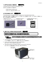
The following parts are supplied with the kit.  Make sure you have all items shown below. 

本キットには、下記パーツが付属しています。すべて揃っていることを確認してください。万一不足している場合は、お
買い上げの販売店までご連絡ください。 

Serial I/F Card (1 pc.) 

シリアルインターフェースボード(1枚)


M-3x6 Screw (2 pcs.) 

ネジ

 M-3x6 

(2本)


Installation Manual (1 copy

組込説明書(本書)


3. INSTALLATION PROCEDURE


組込手順


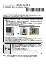
本書は

B-EX4T

海外モデルの写真を使用しており国内モデルとは外観や標準装備品が異なりますが、組込手

順は共通です。


1.  Turn the printer power off and disconnect the Power Cord. 


プリンタの電源スイッチを OFF にし、電源プラグをコンセントから抜きます。 

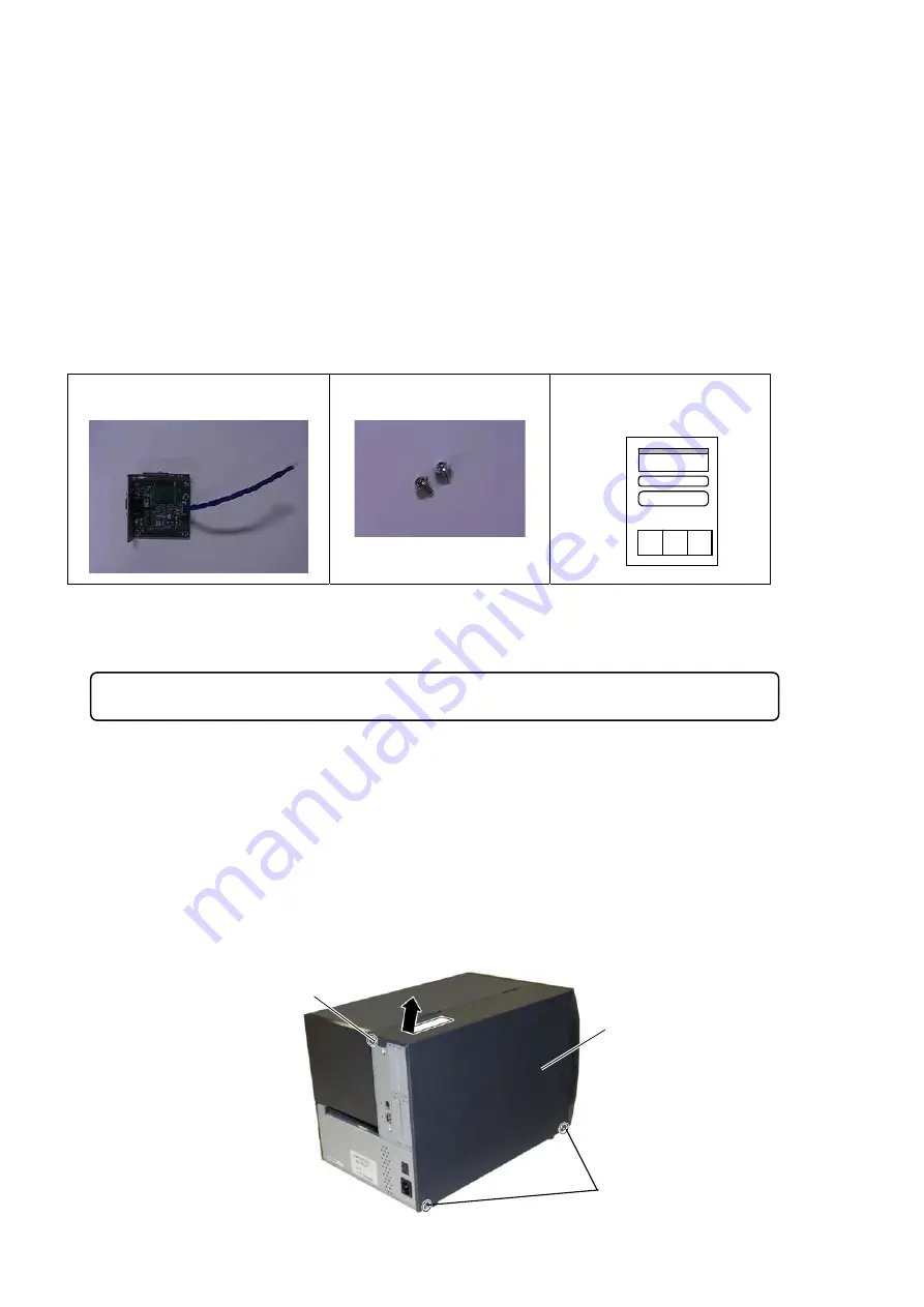
2.  Remove the three B-4x5 screws from the Side Panel (L). 


左サイドカバーからネジ3本(B-4x5)を外します。 

3.  Slide the Side Panel (L) backward, and raise it to remove from the printer.  


左サイドカバーを本体後方側へスライドさせ、持ち上げて外します。  


B-4x5 Screw 

ネジ

B-4x5


Side Panel (L) 

左サイドカバー


B-4x5 Screw 

ネジ

B-4x5


重要:プリンタの電源をオフした後、1分以上経過するまでお待ちください。 
Summary of Contents for B-EX700-RS-QM-R

Page 1: ...Failure to follow manual instructions or any unauthorized modifications substitution or change to this product will void the limited product warranty 2 Turn the power off and disconnect the power cord before installing this optional kit 3 Be careful not to pinch your fingers or hands with the covers 4 The print head and stepping motor becomes very hot immediately after printing Do not touch the pr...

Page 2: ...Card 1 pc シリアルインターフェースボード 1枚 M 3x6 Screw 2 pcs ネジ M 3x6 2本 Installation Manual 1 copy 組込説明書 本書 3 INSTALLATION PROCEDURE 組込手順 本書は B EX4T 海外モデルの写真を使用しており国内モデルとは外観や標準装備品が異なりますが 組込手 順は共通です 1 Turn the printer power off and disconnect the Power Cord プリンタの電源スイッチを OFF にし 電源プラグをコンセントから抜きます 2 Remove the three B 4x5 screws from the Side Panel L 左サイドカバーからネジ3本 B 4x5 を外します 3 Slide the Side Panel L backward and ...

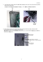
Page 3: ...し プリンタ後部から目隠し板を引き抜きます 5 Fit the Serial Connector of the Serial Interface Board into the slot from the inside and secure it with the two M 3x6 screws from the outside as shown below 目隠し板を外したスロットにプリンタの内側からパラレルインターフェースボードのコネクタを差し込み 外側からネ ジ2本 M 3x6 で固定します Serial Interface Connector シリアルインターフェースボードのコネ クタ M 3x6 Screw ネジ M 3x6 M 3x6 Screw ネジ M 3x6 Blind Plate 目隠し板 Tab ツメ Tab ツメ ...

Page 4: ... EX6T series J8 connector for B EX4T series 7 Re install the Side Panel L 左サイドカバーをプリンタに取り付けます 8 Refer to the Service Manual for the interface parameter settings サービスマニュアルを参照してインターフェースに関連するパラメータ設定を行ってください J6 J8 Main PC Board メイン PC 板 Interface Cable インターフェースケーブル Serial Interface Board シリアルインターフェース ボード PRINTED IN INDONESIA EO2 38080C 東芝テック株式会社 2017 ...

Reviews: