background image


D4163443A 


Ultra-High-Resolution CMOS   

Monochrome Camera 

CSC12M25BMP19 

Operation manual 


Contents 


BEFORE USE - GENERAL SAFETY INSTRUCTIONS .................1 
CASES FOR INDEMNITY (LIMITED WARRANTY).....................4 
RESTRICTION FOR USE..................................................................4 
Usage Precautions ...............................................................................5 
1. Outline .............................................................................................8 
2. Characteristic...................................................................................8 
3. Configuration...................................................................................9 
4. Option..............................................................................................9 
5. Installation .....................................................................................10 
6. Cabling ..........................................................................................11 
7. Maintenance port...........................................................................12 
8. Specification..................................................................................12 
9. Command Communication Protocol .............................................21 
10. Register map................................................................................23 
11. Function .......................................................................................25 
12. External-view Drawing ...............................................................29 


Summary of Contents for CSC12M25BMP19

Page 1: ...NSTRUCTIONS 1 CASES FOR INDEMNITY LIMITED WARRANTY 4 RESTRICTION FOR USE 4 Usage Precautions 5 1 Outline 8 2 Characteristic 8 3 Configuration 9 4 Option 9 5 Installation 10 6 Cabling 11 7 Maintenance port 12 8 Specification 12 9 Command Communication Protocol 21 10 Register map 23 11 Function 25 12 External view Drawing 29 ...

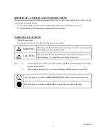
Page 2: ...en below Notes 1 Personal injury means wounds burns electric shocks and others for which hospitalization or long term care are not required 2 Material damage means any direct or consequential damage related to property or material loss WARNING This mark warns the user that improper use may cause death or severe personal injury of the user or people in the vicinity CAUTION This mark warns the user ...

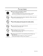
Page 3: ...l apart Do not disassemble repair or modify the equipment Otherwise fire or electric shock may result For internal repair inspection or cleaning contact your sales representative Avoid Do not place anything on the equipment If metallic objects liquid or other foreign matter enters the equipment fire or electric shock may result Avoid Do not install the equipment in an unstable or inclined location...

Page 4: ...cations exposed to direct sunlight or humidity Otherwise the internal temperature of the equipment will rise which may cause a fire Avoid Use only specified DC power cables and connection cables Otherwise fire or electric shock may result Avoid When performing connection turn off power When connecting the power cable or connection cable turn off the equipment power Otherwise fire or electric shock...

Page 5: ...nments give consideration to safety measures and inform us of such usage 1 Use of the equipment in the conditions or environment contrary to those specified or use outdoors 2 Use of the equipment in applications expected to cause potential hazard to people or property which require special safety measures to be adopted This product can be used under diverse operating conditions Determination of ap...

Page 6: ...on Occurrence of moiré If you shoot thin stripe patterns moiré patterns interference fringes may appear This is not a malfunction Occurrence of noise on the screen If an intense magnetic or electromagnetic field is generated near the camera or connection cable noise may be generated on the screen If this occurs move the camera or the cable Handling of the protective cap If the camera is not in use...

Page 7: ...atrix in a plane for a CMOS image sensor If any of those photo sensor elements is defective the image of the area including the element is not displayed which generates a white or black flaw on the monitor screen The quantity and the brightness of the flaw increase in a higher temperature condition than the normal temperature condition It also increases when the exposure time is longer The flaw ma...

Page 8: ...毒有害物质的 限量要求标准规定的限量要求 SJ T11363 2006 This information is applicable for People s Republic of China only リサイクル リサイクル リサイクル リサイクルに に に に関 関 関 関する する する する情報 情報 情報 情報 包装物 包装物 包装物 包装物 有关再利用的信息 有关再利用的信息 有关再利用的信息 有关再利用的信息 包装物 包装物 包装物 包装物 Information on recycling of wrapping composition Information on recycling of wrapping composition Information on recycling of wrapping composition Information on recycli...

Page 9: ...ploys a global electronic shutter similar to a CCD image sensor clear images of even fast moving object are obtainable with less blur 4 Random trigger shutter Photo images can be imported in any timing by inputting external trigger signals 5 Camera link interface Image output and camera control interfaces employ the camera link standard The dual MDR connector supporting Camera Link Medium Configur...

Page 10: ... 1 Instruction manual English 1 Application software is not attached to this camera 4 Option 1 DC IN cable CPRC3700 2 Camera link cable 14B26 SZLB 0LC Sumitomo 3M Recommended cable length 5m or less 3 Camera adaptor CA130C 4 Tripod mounting hardware CPTC12M 5 F mount conversion adaptor FTAR 2 NOTE Contact your dealer distributor for details of option units Conformity of optional peripherals and EM...

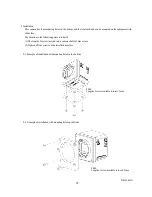
Page 11: ...the following points to install it 1 The length of a screw inserted into a camera shall be 5mm or less 2 Tighten all four screws on the installation surface 5 1 Example of installation with mounting holes on the bottom 5 2 Example of installation with mounting holes on the front 4 M4 Length of screw available to insert 5mm 4 M4 Length of screw available to insert 5mm ...

Page 12: ...Do not bend the cable in smaller radius than the minimum bending radius described below Otherwise it may break the cable Check with the cable maker for handling the minimum bending radius if other cables than options shown below are used Option cable Cable Model Maker Static minimum bending radius recommended value Camera link cable 14B26 SZLB 0LC Sumitomo 3M Ltd 90mm Power cable CPRC3700 TOSHIBAT...

Page 13: ... 1 9 type 2 Scan mode Progressive 3 Aspect ratio 4 3 4 Synchronization system Internal synchronization 5 Standard object illuminance 2000 lx F value 5 6 3000 K 6 Minimum object illuminance 30 lx F2 8 GAIN MAX reading all pixels image level 50 7 Image output Compliant to the camera link standard Output mode Switchable between Base and Medium configuration Factory setting Medium configuration Data S...

Page 14: ...g Pulse width mode The exposure time depends on the external trigger pulse width Minimum pulse width 50 µsec Minimum exposure time 50 µsec Internal synchronous signal specification 1 Scan frequency Reading mode When the shutter is OFF Reading all pixels Horizontal Approx 75 kHz Vertical Approx 25 Hz Binning Horizontal Approx 67 kHz Vertical Approx 43 5 Hz Sub sampling Horizontal Approx 75 kHz Vert...

Page 15: ...ome lenses may not exert full performance of a camera including the decline in the peripheral resolution the decline in the reduction of brightness generation of ghost and aberration Please check the combination with this camera for the lens being used Use a TFL II mount lens whose projecting part from the seating face is 8 1mm or less to be used combined with this camera 2 Dimension 75 mm W 75 mm...

Page 16: ...ation 3 Storage temperature Temperature 20 to 60 C Humidity 90 or less No dew formation Representative spectral sensitivity characteristic Note that the lens characteristic and the light source characteristic are excluded Various safety standards 1 EMC condition Electro Magnetic Compatibility EMI Electro Magnetic Interference EN61000 6 4 2001 to be acquired EMS Electro Magnetic Susceptibility EN61...

Page 17: ... CLK OUT 18 O X CLK OUT 6 O X3 19 O X3 7 I Ser TC RxD 20 I Ser TC RxD 8 O Ser TFG TxD 21 O Ser TFG TxD 9 I CC1 TRIG 22 I CC1 TRIG 10 I CC2 MULTI 23 I CC2 MULTI 11 I CC3 24 I CC3 12 I CC4 25 I CC4 13 GND 26 GND Connector CAMERALINK2 Pin No I O Signal Pin No I O Signal 1 GND 14 GND 2 O Y0 15 O Y0 3 O Y1 16 O Y1 4 O Y2 17 O Y2 5 O Y CLK OUT 18 O Y CLK OUT 6 O Y3 19 O Y3 7 100Ω terminated 20 20 100Ω t...

Page 18: ...TRIG 12 GND Switch setting Various settings are available with the dip switch on the back Memory bank specified Communication speed setting Switching output mode O N 1 2 3 4 5 6 7 8 Unused indicates default setting at shipment 1 Switching output mode Switch between Medium Configuration and Base Configuration The power of the camera needs be turned on again to switch modes SW1 Output mode OFF Mediu...

Page 19: ...0 bps OFF ON 38400 bps ON ON 57600 bps 3 Specifying a memory bank before starting Specify a memory bank to be referenced before turning on the power of the camera for SW4 through SW6 The power of the camera needs be turned on again to switch modes SW4 SW5 SW6 Memory bank OFF OFF OFF Bank 1 ON OFF OFF Bank 2 OFF ON OFF Bank 3 ON ON OFF Bank 4 OFF OFF ON Bank 5 ON OFF ON Bank 6 OFF ON ON Bank 7 ON O...

Page 20: ...ation The figure in parentheses indicates that for Base configuration 1 Reading all pixels LVAL DATA OUT1 4 DATA OUT1 2 a f a 1048 2096 CLK b 4 8 CLK c 1024 2048 CLK c d FVAL CLK 82 5MHz b e d 8 16 CLK e 16 32 CLK f 1052 2104 CLK DVAL 2 CLK rate Medium Configuration ...

Page 21: ...m configuration Figures in parentheses are for Base configuration 1 Reading all pixels when the shutter is OFF FVAL DATA OUT1 4 DATA OUT1 2 LVAL A B A 20 2usec 40 4usec B 39 22msec 78 44msec C 12 8usec 25 6usec D 39 25msec 78 5msec C D CLK 82 5MHz Note The frame rate changes according to the shutter speed when the shutter is ON The period A in the chart indicates the period of the shutter speed ...

Page 22: ...max length is 2 bytes and Data s max length is 8 bytes For example to write data 0x38 to address 0x76 send a command as follows The camera responds to the write command with No Error ACK or Error NAK as follows No Error ACK Error NAK Because two kinds of data is needed for the setting Approx the Partial Scan the register writing for Set value application is separately needed Address 2nd byte Addre...

Page 23: ...ponds to the read request as follows Data s max length is 8 bytes Actually the camera responds to the read request as minimum data length For example to read data 0x10 to address 0x91 the camera responds as follows 9 0x39 1 0x31 0x2C R 0x52 Q 0x51 CR 0x0D Data 8thby te Data 7thby te Data 6thby te Data 5thby te Data 4thby te Data 2ndby te Data 1stby te CR 0x0D Data 3rdby te 1 0x31 0 0x30 CR 0x0D ...

Page 24: ...d status Extended status Store detail information corresponding to the status Call memory Call memory Call memory Call memory Write memory bank number 0 Call default setting Write memory bank number 1 8 Call a setting from the specified number Read registers Check the memory number used Use 0 if no memory has been called Initialize memory Initialize memory Initialize memory Initialize memory Write...

Page 25: ... user area 0x01 write Erase the user area Specify user area data Specify user area data Specify user area data Specify user area data Write or read data to from the address specified by the user area data specified register When data is set to this register data is written to the address specified by the address specified register The address to which nothing has been written is initialized by 0x0...

Page 26: ...els The camera reads all pixels 4096 H 3072 V pixels inApprox 25 fps 2 Binning The camera reads all effective areas in Approx 43 5fps by binning 2x2 for all pixels 4096 H 3072 V pixels As it reads adjacent 4 pixels as one pixel the resolution reduces However as the pixel noise is averaged it can output lower noise than that is produced when it reads all pixels Complex operation with WOI and sub sa...

Page 27: ...he polarity is set to negative polarity Random trigger shutter operates in either the fixed mode and the pulse width mode and has different ways to determine the exposure time depending on the mode Film cannot be exposed during reading images using the random trigger shutter If inputting triggers is to be continued input them after finishing image output of the camera 1 Fixed mode The exposure tim...

Page 28: ... horizontal and vertical directions Area setting has the following conditions Number of windows 1 to 28 Setting position H Integral multiple of 4 columns V Integral multiple of one row Window size H Integral multiple of 4 columns minimum size 16 V Integral multiple of one row minimum size 2 Overlapping of windows Possible Others 1 Frame rate There is no proportional relation between the window are...

Page 29: ...he image output of the line 1 When multiple windows are set on the same line 2 When multiple windows overlap 11 4 Multi slope to be implemented An apparently wide dynamic range is obtainable through exposure up to four times Note that the tone may not be correctly represented for the point where the slope switches Fixed pattern noise may increase depending on the setting ...

Page 30: ...ernal view Drawing Dip switch Maintenance port Design specification Material Lens mount Cover Aluminum die cast Chassis Cold rolled steel Processing Lens mount Cover Cation resistant aluminum alloy Chassis Nickel plating ...

Page 31: ...D4163443A 30 Note ...
Page 32: ...1 4 chome Asahigaoka Hino shi Tokyo 191 0065 Japan Overseas Sales Department Phone 81 42 589 8771 Fax 81 42 589 8774 URL http www toshiba teli co jp The design and specification is subject to change without notice Distributer ...

Reviews: