– 24 –
Fig. 8-4-6
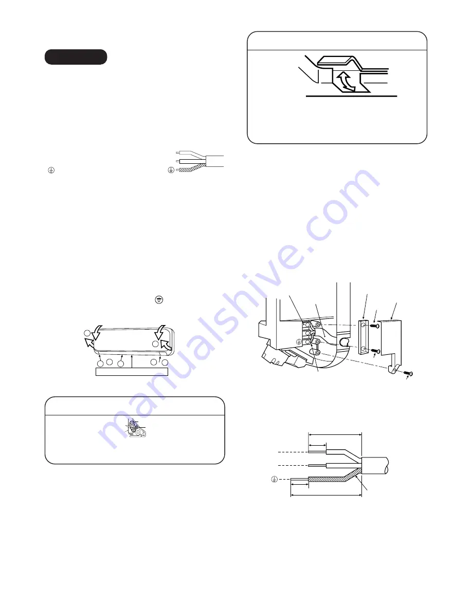
How to open the screw cap
• Place your finger on the lower part and push
up to open the screw cap.
(1) Open the screw caps and remove the two screws
securing the front cabinet.
(2) Close the screw caps as behind.
(3) Open the vertical airflow louver horizontally by
hand.
(4) Slightly open the lower part of the front cabinet
then pull the upper part of the front cabinet toward
you to remove it from the rear plate.
Taking out the power cord
• Cut off the slitted portion in the side face of the
rear panel to take out the power cord. After
this, remove burrs, sharp edges, etc., to
smooth the cut face.
<How to connect the power cord>
For the air conditioner that has no power cord,
connect a power cord to it as mentioned below.
• After removing the front cabinet, remove the
terminal cover and the cord clamp.
• Connect and secure the power supply cord and
secure the cord clamp and the terminal cover.
• Cut the rear panel following the cutting mark and
put the power supply cord through the notch.
• Be sure to smooth out the notch with a file, etc.
8-4-3. Wiring Connection
WARNING
To plug the cable in the plug receptacle, take the
following precaution.
THIS APPLIANCE MUST BE EARTHED.
IMPORTANT
THE WIRES IN THIS MAINS LEAD ARE COLORED
IN ACCORDANCE WITH THE FOLLOWING CODE:
Fig. 8-4-5
As the colors of the flexible cord of this appliance may
not correspond with the colored markings, to identify
terminals in your plug, as follows:
Connect BROWN colored core to plug terminal marked
letter "L".
Connect BLUE colored core to plug terminal marked
letter "N".
Connect GREEN AND YELLOW colored core to plug
terminal marked Earth Symbol "
".
<How to remove the front cabinet>
Fig. 8-4-7
<Stripping length of power cord>
3
2
2
1
1
4
4
Vertical air flow louver.
L
N
L
N
-LIVE
-NEUTRAL
-EARTH
: Brown
: Blue
: Green and Yellow
Earth line
40mm
10mm
10mm
30mm
L
N
Cord clamp
Terminal cover
Screw
Power supply
cord
Terminal block
Earth line
Screw
Screw
L
N
NOTE :
• Use standard wire only.
• Wire type: More than H05-RN-F
Fig. 8-4-8
Indoor unit
Connecting
cable
Installation
plate
Auxiliary
pipes
Summary of Contents for 10SAX-1
Page 46: ... 46 9 4 2 PC Board Layout BottomView Top View ...
Page 56: ......


